AC MACHINES-1 (66761) Theory
13. Understand the equivalent circuit and maximum Power output of an induction motor.
13.1. Explain the equivalent circuit of an induction motor.
Equivalent Circuit for an Induction Motor
An induction motor is a well-known device which works on the principle of transformer. So it is also called the rotating transformer. That is, when an EMF is supplied to its stator, then as a result of electromagnetic induction, a voltage is induced in its rotor. So an induction motor is said to be a transformer with rotating secondary. Here, primary of transformer resembles stator winding of an induction motor and secondary resembles rotor.
The induction motor always runs below the synchronous or full load speed and the relative difference between the synchronous speed and speed of rotation is known as slip which is denoted by s.
Where, Ns is synchronous speed of rotation which is given by-
Where, f is the frequency of the supply voltage.
P is the number of poles of the machine.
Equivalent Circuit of an Induction Motor
The equivalent circuit of any machine shows the various parameter of the machine such as its Ohmic losses and also other losses.
The losses are modeled just by inductor and resistor. The copper losses are occurred in the windings so the winding resistance is taken into account. Also, the winding has inductance for which there is a voltage drop due to inductive reactance and also a term called power factor comes into the picture. There are two types of equivalent circuits in case of a three-phase induction motor-
Exact Equivalent Circuit
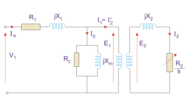
Here, R1 is the winding resistance of the stator.
X1 is the inductance of the stator winding.
Rc is the core loss component.
XM is the magnetizing reactance of the winding.
R2/s is the power of the rotor, which includes output mechanical power and copper loss of rotor.
If we draw the circuit with referred to the stator then the circuit will look like-
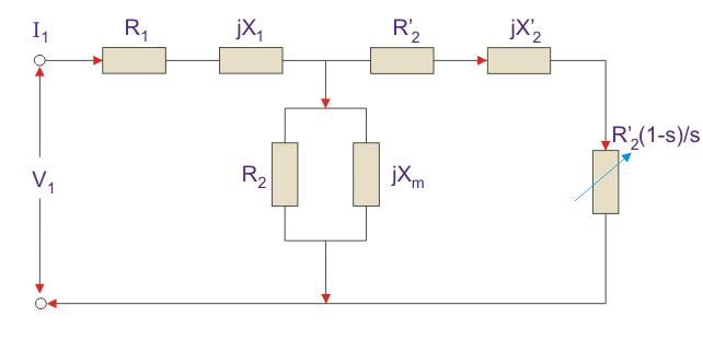
Here all the other parameters are same except-
R2’ is the rotor winding resistance with referred to stator winding.
X2’ is the rotor winding inductance with referred to stator winding.
R2(1 – s) / s is the resistance which shows the power which is converted to mechanical power output or useful power. The power dissipated in that resistor is the useful power output or shaft power.
Approximate Equivalent Circuit
The approximate equivalent circuit is drawn just to simplify our calculation by deleting one node. The shunt branch is shifted towards the primary side. This has been done as the voltage drop between the stator resistance and inductance is less and there is not much difference between the supply voltage and the induced voltage. However, this is not
appropriate due to following reasons-
- The magnetic circuit of induction motor has an air gap so exciting current is larger compared to transformer so exact equivalent circuit should be used.
- The rotor and stator inductance is larger in induction motor.
- In induction motor, we use distributed windings.
This model can be used if approximate analysis has to be done for large motors. For smaller motors, we cannot use this.
Power Relation of Equivalent Circuit
- Input power to stator- 3 V1I1Cos(Ɵ).
Where, V1 is the stator voltage applied.
I1 is the current drawn by the stator winding.
Cos(Ɵ) is the stator power stator. - Rotor input =
Power input- Stator copper and iron losses. - Rotor Copper loss = Slip × power input to the rotor.
- Developed Power = (1 – s) × Rotor input power.
Equivalent Circuit of a Single Phase Induction Motor
There is a difference between single phase and three phase equivalent circuits. The single phase induction motor circuit is given by double revolving field theory which states that-
A stationary pulsating magnetic field might be resolved into two rotating fields, both having equal magnitude but opposite in direction. So the net torque induced is zero at standstill. Here, the forward rotation is called the rotation with slip s and the backward rotation is given with a slip of (2 – s). The equivalent circuit is-
In most of the cases the core loss component r0 is neglected as this value is quite large and does not affect much in the calculation.
Here, Zf shows the forward impedance and Zb shows the backward impedance.
Also, the sum of forward and backward slip is 2 so in case of backward slip, it is replaced by (2 – s).
R1 = Resistance of stator winding.
X1 = Inductive reactance of the stator winding.Xm = Magnetising reactance.
R2’ = Rotor Reactance with referred to stator.
X2’ = Rotor inductive reactance with referred to stator.Calculation of Power of Equivalent Circuit
- Find Zf and Zb.
- Find stator current which is given by Stator voltage/Total circuit impedance.
- Then find the input power which is given by
Stator voltage × Stator current × Cos(Ɵ)
Where, Ɵ is the angle between the stator current and voltage. - Power Developed (Pg) is the difference between forward field power and backward power. The forward and backward power is given by the power dissipated in the respective resistors.
- The rotor copper loss is given by- slip × Pg.
- Output Power is given by-
Pg – s × Pg – Rotational loss.
The rotational losses include friction loss, windage loss, Core loss. - Efficiency can also be calculated by diving output power by input power
Induction Motor Equivalent Circuit
From the preceding, we can utilise the equivalent circuit of a transformer to model an induction motor.
_thumb.png "Induction Motor Equivalent Circuit (1)")
In the equivalent circuit R1 represents, the resistance of the stator winding and X1 the stator leakage reactance (flux that does not link with the air gap and rotor). Magnetising reactance required to cross the air gap is represented by Xm and core losses (hysteresis and eddy current) by Rc.
An ideal transformer of N1 and N2 turns respectively represents the air gap. For the rotor side, the induced emf is affected by the slip (as the rotor gains speed, slip reduces and less emf is induced). The rotor resistance and reactance are represented by R2 and X2; with X2 being dependant on the frequency of the inductor rotor emfs.
The rotor circuit, the current I2 is given by:
_thumb.png "Image(39)")
which can be rewritten as:_thumb.png "Image(40)")
The above equality allows the equivalent circuit to be drawn as:

Simplified Equivalent Circuit
The equivalent circuit shown above has removed the dependence on slip for determining the secondary voltage and frequency. Consequently the circuit can be simplified by eliminating the ideal transformer and referring the rotor's resistance and reactance to the primary (denoted by ′).

The referred values are calculated by multiplying them by k2, where k is the effective stator/rotor turns ratio.
Note: it is relatively straightforward to obtain the equivalent circuit parameters by testing. Typically this would involve a d.c. test, no-load test and locked rotor test.


_2.png "Induction Motor Equivalent Circuit (1)")
_2.png "Image(39)")
_2.png "Image(40)")

