DATA COMMUNICATION SYSTEM
| Site: | jpilms.gnomio.com |
| Course: | Data Communication System |
| Book: | DATA COMMUNICATION SYSTEM |
| Printed by: | Guest user |
| Date: | Friday, 4 April 2025, 1:33 AM |
Table of contents
- 1. Syllabus
- 2. 1. Understand the communication(basics.)(chapter 1)
- 3. Understand Digital Communication( Chapter 3) Systems
- 4. Understand the transmission media and connectors. (Chapter4)
- 5. Understand multiplexing techniques (Chapter 5)
- 6. Understand computer network basics.(chapter 6)
- 6.1. Define Computer Network
- 6.2. State the concept of computer Network
- 6.3. Mention elements of computer network
- 6.4. Describe the advantages of Computer network.
- 6.5. Describe the application of computer network.
- 6.6. Describe client / server and peer-to-peer network.
- 6.7. Describe the general features of LAN, MANs and WANs
- 7. Chapter 07.Understand the network topologies.
- 7.1. Define network topology.
- 7.2. Describe the physical connection of bus, ring, star, mesh and hybrid topologies
- 7.3. Mention the advantages and disadvantages of bus, ring, star, mesh and hybrid topologies.
- 7.4. the key factors you should pay attention to when choosing a network topology.
- 7.5. Describe the logical topologies of a token ring network.
- 8. Definition of Protocol (Chapter 8)
- 9. Understand IP addressing. (chapter 9)
- 10. Understand Network Interface Cards (NIC) (chapter 10)
- 11. Understand the connectivity devices (chaptere 11)
1. Syllabus
Theory: 1. Understand the communication basics.
1.1 Define Electronic Communication.
1.2 Mention the basic elements of a communication system.
1.3 Describe communication system with a simple block diagram.
1.4 State the terms: Frequency,Wavelength,Spectrum, Bandwidth, Throughput,Propagation speed,
Propagation time, Noise figure & SNR
1.5 Mention the difference between bandwidth and data rate.
1.6 Describe simplex, half-duplex and full duplex modes of communication.
1.7 Describe synchronous and asynchronous communication techniques.
2. Understand Analog Communication Systems
2.1 Define Modulation and Demodulation.
2.2 State the necessity of modulation.
2.3 Mention the types of modulation.
2.4 Describe Amplitude, Frequency and Phase modulation with necessary waveform.
2.5 State the difference between analog and digital modulation
2.6 State the advantage and disadvantages of ASK, FSK and PSK (BPSK)
3. Understand Digital Communication Systems
3.1 Define digital modulation.
3.2 Describe Digital communication system with block diagram.
3.3 Define Line Coding and Block Coding.
3.4 Mention the Line Coding Schemes.
3.5 State unipolar Linecoding with timing diagram.
3.6 Describe NRZ-I Line Coding scheme using 4B/5B Block Coding.
3.7 Describe different types of polar encoding with necessary timing diagram.
4. Understand the transmission media and connectors.
4.1 Mention the categories of transmission media
4.2 Describe the construction of Twisted-pair (STP, UTP) Co-axial and Fiber optic cable.
4.3 State the characteristics of Twisted-pair (STP, UTP), Co-axial and Fiber optic cable.
4.4 State the advantage and disadvantages of each type of cables.
4.5 Define Wireless Media and Propagation.
4.6 Describe Wireless Propagation Modes with diagram.
4.7 Describe the method of Radio, Microwave and Infrared communication system.
4.8 State the characteristics of Radio, Microwave and Satellite communication system.
5. Understand multiplexing techniques
5.1 Define Multiplexing and De-multiplexing process of communication system.
5.2 State the necessity of multiplexing.
5.3 Mention the categories of multiplexing.
5.4 Define Frequency division multiplexing.
5.5 Describe Frequency division multiplexing and de-multiplexing technique with block diagram
5.6 Describe the Wave division multiplexing and De-multiplexing technique with block diagram
5.7 Define Time division multiplexing and of Code division multiplexing system
5.8 State difference between baseband and broadband transmission.
6. Understand computer network basics.
6.1 Define Computer Network
6.2 State the concept of computer Network.
6.3 Mention elements of computer network.
6.4 Describe the advantages of Computer network.
6.5 Describe the application of computer network.
6.6 Describe client / server and peer-to-peer network.
6.7 Describe the general features of LAN, MANs and WANs.
7. Understand the network topologies.
7.1 Define network topology.
7.2 Mention the difference between physical and logical topology.
7.3 Describe the physical connection of bus, ring, star, mesh and hybrid topologies.
7.4 Mention the advantages and disadvantages of bus, ring, star, mesh and hybrid topologies.
7.5 Describe the factors to select a particular topology.
7.6 Describe the logical topologies of a token ring network.
8. Understand network protocols.
8.1 Define network protocol.
8.2 Describe the main elements of protocol.
8.3 Describe the characteristics of protocol.
8.4 Describe the functions of protocol.
8.5 List different types of network protocols.
8.6 State the function of TCP/IP protocol.
9. Understand IP addressing.
9.1 Define Network Addressing.
9.2 Define IP and IPv4
9.3 Describe the IP address formats of class A,B,C,D &E with example.
9.4 Describe subnet and subnet masks.
9.5 State CIDR format of subnet.
9.6 Define IPv6.
9.7 Describe the address format of IPv6.
10. Understand Network Interface Cards (NIC)
10.1 State the role of NIC.
10.2 Describe the format of Physical address (MAC Address) of NIC.
10.3 Mention the points that agree both the sending and receiving NICs.
10.4 State the importance of base memory address for NIC.
10.5 Mention the important points to maintain the compatibility among NIC, bus and cables.
10.6 Describe the NIC related factors that enhanced the performance of network.
11. Understand the connectivity devices
11.1 List the connectivity devices used in networking.
11.2 Describe function of MODEM.
11.3 Describe MODEM types and Standard.
11.4 Describe the features of ADSL and Digital MODEM.
11.5 Describe the functions of Hubs, Repeaters and switches in network.
11.6 Describe the important features of Repeaters and switches.
11.7 Describe the functions of Router and Gateway
Practical: Identify different types of guided communication media.
1. Twisted Pair Cable- Unshielded Twisted Pair (UTP), Shielded Twisted Pair (STP) 2. Co-axial Cable- Thick net and Thin net 3. Fiber Optic Cable- Single mode and Multi mode 4. Constructional features of UTP, STP, Co-axial Cable and Fiber Optic Cable.
Identify different types of connectors
5. Twisted Pair Cable- RJ45 Connectors and their constructional features. 6. Co-axial Cable- BNC Connectors and their constructional features. 7. Fiber Optic Cable- MT-RJ and their constructional features. Identify other Network hardware’s
8. Network Interface Cards/LAN cards/ Network Adaptor. 9. Cable Tester, Crimper and Accessories 10. Modems, Hubs, Repeater, Switch & Router
Connect RJ45 Connector with UTP Cable
11. Make a straight through cable 12. Make a Cross over cable 13. Make a console cable
Establish a Peer to Peer/Workgroup LAN
14. Install Network Interface Card (NIC) into the PC 15. Check the MAC address of the Network Interface Card (NIC) 16. Connect straight cable or cross over cable among PCs, Hub or Switch 17. Configure the TCP/IP in each PC 18. Test the connectivity among PCs using Ping Command.
Perform the task to Work with a Peer/Workgroup LAN environment for simple data communication.
19. Share the folders, Pen drive and Secondary memory. 20. Share a printer, DVD Drive or any other resources.
Establish a Client–Server Local Area Network
21. Install Windows server 2012 into a server PC 22. Configure TCP/IP to server and client PCs 23. Perform the task to configure the Active Directory 24. Perform the task to configure The DNS. 25. Perform the task to configure the DHCP 26. Perform the task to Work with a Client–Server LAN environment for simple datacommunication and Administrative functions.
REFERENCE BOOKS
1. Data communications and Networking – Behrouz A. Forouzan. 2. Fundamentals of Communication-M. Shamim Kaiser and associates
4. Data and Computer Communications-William Stallings 5. Local Area Networking – S. K Basandra. 6. MCSE Windows & Networking Essential – Joe Casad
2. 1. Understand the communication(basics.)(chapter 1)
1.1 Define Electronic Communication.
1.2 Mention the basic elements of a communication system.
1.3 Describe communication system with a simple block diagram.
1.4 State the terms: Frequency,Wavelength,Spectrum, Bandwidth, Throughput,Propagation speed,
Propagation time, Noise figure & SNR
1.5 Mention the difference between bandwidth and data rate.
1.6 Describe simplex, half-duplex and full duplex modes of communication.
1.7 Describe synchronous and asynchronous communication techniques.
1.1 Define Electronic Communication.
Electronic communications are defined in the ECPA as data communications carried over both wire and wireless systems. Electronic communications differ from wire communications in that they are communications that are not transmitted by sound waves and cannot be characterized as containing a human voice.
2.1. Define Electronic Communication.
Electronic communication
Electronic communication is the meaningful exchange of information at a distance by technological means, particularly through electrical signals or electromagnetic waves.
2.2. Mention the basic elements of a communication system.
The basic elements of a communication system
The basic components of a communication system are information source, input transducer, transmitter, communication channel, receiver, output transducer, and destination.
2.3. Describe communication system with a simple block diagram.
communication system with a simple block diagram.
1.Information source :-
The objective of any communication system is to convey information from one point to the other. The information comes from the information source, which originates it
Information is a very generic word signifying at the abstract level anything intended for communication, which may include some thoughts, news, feeling, visual scene, and so on.
The information source converts this information into physical quantity.
The physical manifestation of the information is termed as message signal
2.Transmitter :-
The objective of the transmitter block is to collect the incoming message signal and modify it in a suitable fashion (if needed), such that, it can be transmitted via the chosen channel to the receiving point.
Channel is a physical medium which connects the transmitter block with the receiver block.
The functionality of the transmitter block is mainly decided by the type or nature of the channel chosen for communication.
3.Channel :-
Channel is the physical medium which connects the transmitter with that of the receiver.
The physical medium includes copper wire, coaxial cable, fibre optic cable, wave guide and free space or atmosphere.
The choice of a particular channel depends on the feasibility and also the purpose of the communication system.
4.Receiver:-
The receiver block receives the incoming modified version of the message signal from the channel and processes it to recreate the original (non-electrical) form of the message signal.
There are a great variety of receivers in communication systems, depending on the processing required to recreate the original message signal and also final presentation of the message to the destination.
5.Destination:-
The destination is the final block in the communication system which receives the message signal and processes it to comprehend the information present in it.
Usually, humans will be the destination block.
3. Understand Digital Communication( Chapter 3) Systems
3.1 Define digital modulation.
3.2 Describe Digital communication system with block diagram.
3.3 Define Line Coding and Block Coding.
3.4 Mention the Line Coding Schemes.
3.5 State unipolar Linecoding with timing diagram.
3.6 Describe NRZ-I Line Coding scheme using 4B/5B Block Coding.
3.7 Describe different types of polar encoding with necessary timing diagram.
3.1 Define digital modulation.
DM stands for Digital Modulation and is a generic name for modulation techniques that uses discrete signals to modulate a carrier wave. In comparison, FM and AM are analog techniques. The three main types of digital modulation are Frequency Shift Keying (FSK), Phase Shift Keying (PSK) and Amplitude Shift Keying (ASK).
3.2 Describe Digital communication system with block diagram.
4. Understand the transmission media and connectors. (Chapter4)
4.1 Mention the categories of transmission media
4.2 Describe the construction of Twisted-pair (STP, UTP) Co-axial and Fiber optic cable.
4.3 State the characteristics of Twisted-pair (STP, UTP), Co-axial and Fiber optic cable.
4.4 State the advantage and disadvantages of each type of cables.
4.5 Define Wireless Media and Propagation.
4.6 Describe Wireless Propagation Modes with diagram.
4.7 Describe the method of Radio, Microwave and Infrared communication system.
4.8 State the characteristics of Radio, Microwave and Satellite communication system.
4.1 Mention the categories of transmission media
Types of Transmission Media
In data communication terminology, a transmission medium is a physical path between the transmitter and the receiver i.e it is the channel through which data is sent from one place to another. Transmission Media is broadly classified into the following types:
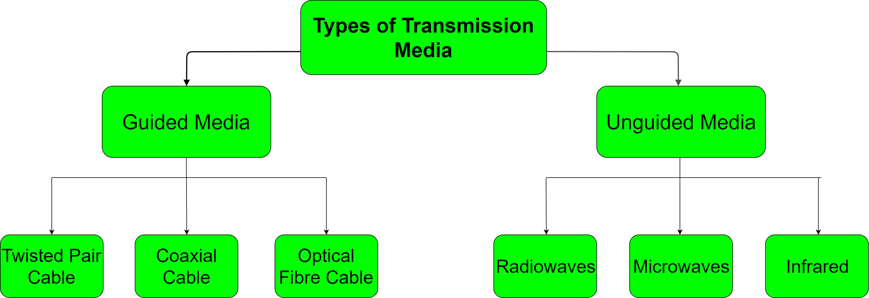
1. Guided Media:
It is also referred to as Wired or Bounded transmission media. Signals being transmitted are directed and confined in a narrow pathway by using physical links.
Features:
- High Speed
- Secure
- Used for comparatively shorter distances
There are 3 major types of Guided Media:
(i) Twisted Pair Cable –
It consists of 2 separately insulated conductor wires wound about each other. Generally, several such pairs are bundled together in a protective sheath. They are the most widely used Transmission Media. Twisted Pair is of two types:
- Unshielded Twisted Pair (UTP):
This type of cable has the ability to block interference and does not depend on a physical shield for this purpose. It is used for telephonic applications.Advantages:
- Least expensive
- Easy to install
- High speed capacity
Disadvantages:
- Susceptible to external interference
- Lower capacity and performance in comparison to STP
- Short distance transmission due to attenuation
- Shielded Twisted Pair (STP):
This type of cable consists of a special jacket to block external interference. It is used in fast-data-rate Ethernet and in voice and data channels of telephone lines.Advantages:
- Better performance at a higher data rate in comparison to UTP
- Eliminates crosstalk
- Comparitively faster
Disadvantages:
- Comparitively difficult to install and manufacture
- More expensive
- Bulky
(ii) Coaxial Cable –
It has an outer plastic covering containing 2 parallel conductors each having a separate insulated protection cover. Coaxial cable transmits information in two modes: Baseband mode(dedicated cable bandwidth) and Broadband mode(cable bandwidth is split into separate ranges). Cable TVs and analog television networks widely use Coaxial cables.
Advantages:
- High Bandwidth
- Better noise Immunity
- Easy to install and expand
- Inexpensive
Disadvantages:
- Single cable failure can disrupt the entire network
(iii) Optical Fibre Cable –
It uses the concept of reflection of light through a core made up of glass or plastic. The core is surrounded by a less dense glass or plastic covering called the cladding. It is used for transmission of large volumes of data.
Advantages:
- Increased capacity and bandwidth
- Light weight
- Less signal attenuation
- Immunity to electromagnetic interference
- Resistance to corrosive materials
Disadvantages:
- Difficult to install and maintain
- High cost
- Fragile
- unidirectional, ie, will need another fibre, if we need bidirectional communication
2. Unguided Media:
It is also referred to as Wireless or Unbounded transmission media.No physical medium is required for the transmission of electromagnetic signals.
Features:
- Signal is broadcasted through air
- Less Secure
- Used for larger distances
There are 3 major types of Unguided Media:
(i) Radiowaves –
These are easy to generate and can penetrate through buildings. The sending and receiving antennas need not be aligned. Frequency Range:3KHz – 1GHz. AM and FM radios and cordless phones use Radiowaves for transmission.
Further Categorized as (i) Terrestrial and (ii) Satellite.
(ii) Microwaves –
It is a line of sight transmission i.e. the sending and receiving antennas need to be properly aligned with each other. The distance covered by the signal is directly proportional to the height of the antenna. Frequency Range:1GHz – 300GHz. These are majorly used for mobile phone communication and television distribution.
(iii) Infrared –
Infrared waves are used for very short distance communication. They cannot penetrate through obstacles. This prevents interference between systems. Frequency Range:300GHz – 400THz. It is used in TV remotes, wireless mouse, keyboard, printer, etc.
5. Understand multiplexing techniques (Chapter 5)
5.1
Define Multiplexing and De-multiplexing process of communication system.
5.2 State the necessity of multiplexing.
5.3 Mention the categories of multiplexing.
5.4 Define Frequency division multiplexing.
5.5 Describe Frequency division multiplexing and de-multiplexing technique with block diagram
5.6 Describe the Wave division multiplexing and De-multiplexing technique with block diagram
5.7 Define Time division multiplexing and of Code division multiplexing system
5.8 State difference between baseband and broadband transmission.
5.1 Define Multiplexing and De-multiplexing process of communication system.
Multiplexing is the process of combining multiple signals into one signal, over a shared medium. If the analog signals are multiplexed, then it is called as analog multiplexing. Similarly, if the digital signals are multiplexed, then it is called as digital multiplexing.
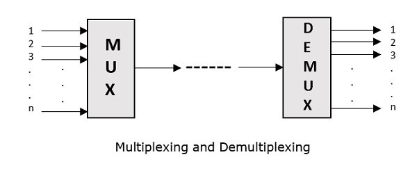
Multiplexing was first developed in telephony. A number of signals were combined to send through a single cable. The process of multiplexing divides a communication channel into several number of logical channels, allotting each one for a different message signal or a data stream to be transferred. The device that does multiplexing can be called as Multiplexer or MUX.
The reverse process, i.e., extracting the number of channels from one, which is done at the receiver is called as de-multiplexing. The device that does de-multiplexing can be called as de-multiplexer or DEMUX.
The following figures illustrates the concept of MUX and DEMUX. Their primary use is in the field of communications.
5.2 State the necessity of multiplexing.
5.3 Mention the categories of multiplexing.
Types of Multiplexers
There are mainly two types of multiplexers, namely analog and digital. They are further divided into Frequency Division Multiplexing (FDM), Wavelength Division Multiplexing (WDM), and Time Division Multiplexing (TDM). There are another multiplexer which is CODE DIVISION Multiplexing .The following figure gives a detailed idea about this classification.
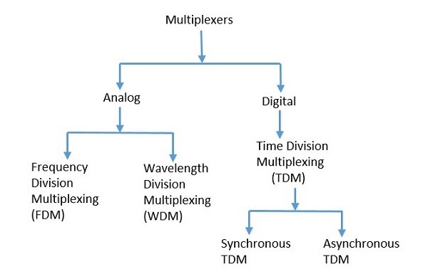
There are many types of multiplexing techniques. Out of which, we have the main types with general classification, mentioned in the above figure. Let us take a look at them individually.
Analog Multiplexing
The signals used in analog multiplexing techniques are analog in nature. The analog signals are multiplexed according to their frequency (FDM) or wavelength (WDM).
Frequency Division Multiplexing
In analog multiplexing, the most used technique is Frequency Division Multiplexing (FDM). This technique uses various frequencies to combine streams of data, for sending them on a communication medium, as a single signal.
Example − A traditional television transmitter, which sends a number of channels through a single cable uses FDM.
Wavelength Division Multiplexing
Wavelength Division multiplexing (WDM) is an analog technique, in which many data streams of different wavelengths are transmitted in the light spectrum. If the wavelength increases, the frequency of the signal decreases. A prism, which can turn different wavelengths into a single line, can be used at the output of MUX and input of DEMUX.
Example − Optical fiber communications use WDM technique, to merge different wavelengths into a single light for communication.
Digital Multiplexing
The term digital represents the discrete bits of information. Hence, the available data is in the form of frames or packets, which are discrete.
Time Division Multiplexing
In Time Division Multiplexing (TDM), the time frame is divided into slots. This technique is used to transmit a signal over a single communication channel, by allotting one slot for each message.
Time Division Multiplexing (TDM) can be classified into Synchronous TDM and Asynchronous TDM.
Synchronous TDM
In Synchronous TDM, the input is connected to a frame. If there are ‘n’ number of connections, then the frame is divided into ‘n’ time slots. One slot is allocated for each input line.
In this technique, the sampling rate is common for all signals and hence the same clock input is given. The MUX allocates the same slot to each device at all times.
Asynchronous TDM
In Asynchronous TDM, the sampling rate is different for each of the signals and a common clock is not required. If the allotted device for a time slot transmits nothing and sits idle, then that slot can be allotted to another device, unlike synchronous
This type of TDM is used in Asynchronous transfer mode networks.
5.4 Define Frequency division multiplexing.
Frequency division multiplexing (FDM) is a technique of multiplexing which means combining more than one signal over a shared medium. In FDM, signals of different frequencies are combined for concurrent transmission.
Concept and Process
In FDM, the total bandwidth is divided to a set of frequency bands that do not overlap. Each of these bands is a carrier of a different signal that is generated and modulated by one of the sending devices. The frequency bands are separated from one another by strips of unused frequencies called the guard bands, to prevent overlapping of signals.
The modulated signals are combined together using a multiplexer (MUX) in the sending end. The combined signal is transmitted over the communication channel, thus allowing multiple independent data streams to be transmitted simultaneously. At the receiving end, the individual signals are extracted from the combined signal by the process of demultiplexing (DEMUX).
Example
The following diagram conceptually represents multiplexing using FDM. It has 4 frequency bands, each of which can carry signal from 1 sender to 1 receiver. Each of the 4 senders is allocated a frequency band. The four frequency bands are multiplexed and sent via the communication channel. At the receiving end, a demultiplexer regenerates the original four signals as outputs.
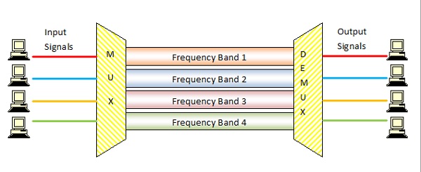
Here, if the frequency bands are of 150 KHz bandwidth separated by 10KHz guard bands, then the capacity of the communication channel should be at least 630 KHz (channels : 150 × 4 + guard bands : 10 × 3).
Uses and Applications
It allows sharing of a single transmission medium like a copper cable or a fiber optic cable, among multiple independent signals generated by multiple users.
FDM has been popularly used to multiplex calls in telephone networks. It can also be used in cellular networks, wireless networks and for satellite communications.
5.5 Describe Frequency division multiplexing and de-multiplexing technique with block diagram
Frequency Division Multiplexing (FDM) System
The operation of frequency division multiplexing (FDM) is based on sharing the available bandwidth of a communication channel among the signals to be transmitted .
This means that many signals are transmitted simultaneously with each signal occupying a different frequency slot within a common bandwidth .
Each signal to be transmitted modulates a different carrier . The modulation can be AM,SSB, FM or PM .
The modulated signals are then added together to form a composite signal which is transmitted over a single channel .
The spectrum of composite FDM signal has been shown in fig.1 .
Fig.1 : Spectrum of FDM Signal
Generally, the FDM systems are used for multiplexing the analog signals .
FDM Transmitter
Fig.2 shows the block diagram of an FDM transmitter .
Fig. 2 : FDM Transmitter
The signals which are to be multiplexed will each modulate a separate carrier .The type of modulation can be AM, SSB, FM or PM .
The modulated signals are then added together to form a complex signal which is transmitted over a single channel .
Working Operation of the FDM Transmitter
Each signal modulates a separate carrier . The modulator outputs will contain the sidebands of the corresponding signals .
The modulator outputs are added together in a linear mixer or adder .
The linear mixer is different from the normal mixers. Here the sum and difference frequency components are not produced . But only the algebraic addition of the modulated outputs will take place .
Different signals are thus added together i the time domain but they have a separate identity in the frequency domain . This is as shown in fig.2 .
The composite signal at the output of mixer is transmitted over the single communication channel as shown in fig.2 . This signal can be used to modulate a radio transmitter if the FDM signal is to be transmitted through air .
FDM Receiver
The block diagram of an FDM receiver is shown in fig.3 .
Fig.3 : FDM Receiver
The composite signal is applied to a group of bandpass filters (BPF) .
Each BPF has a center frequency corresponding to one of the carriers. The BPFs have an adequate bandwidth to pass all the channel information without any distortion .
Each filter will pass only its channel and rejects all the other channels .
The channel demodulator then removes the carrier and recovers the original signal back .
Wavelength Division Multiplexing (WDM)
In fiber communications, the WDM (Wavelength Division Multiplexing) is one type of technology. This is the most useful concept in high-capacity communication systems. At the end of the transmitter section, the multiplexer is used to combine the signals as well as at the end of receiver section, de-multiplexer for dividing the signals separately. The main function of WDM at the multiplexer is for uniting various light sources into an only light source, and this light can be changed into numerous light sources at the de-multiplexer.

5.8 State difference between baseband and broadband transmission.
Key Differences Between Baseband and Broadband Transmission
- Baseband transmission utilizes digital signalling while broadband transmission uses analog signalling.
- Bus and tree topologies, both work well with the broadband transmission. On the other hand, for the baseband transmission bus topology is suitable.
- Baseband involves manchester and differential manchester encoding. In contrast, broadband does not make use of any digital encoding instead it uses PSK (Phase shift keying) encoding.
- The signals can be travelled in both the direction in baseband transmission whereas in broadband transmission the signals can travel in only one direction.
- In baseband transmission, the signals cover shorter distances because at higher frequencies the attenuation is most pronounced which make a signal to travel short distances without reducing its power. As against, in broadband signals, the signals can be travelled at longer distances.
6. Understand computer network basics.(chapter 6)
6.1 Define Computer Network
6.2 State the concept of computer Network.
6.3 Mention elements of computer network.
6.4 Describe the advantages of Computer network.
6.5 Describe the application of computer network.
6.6 Describe client / server and peer-to-peer network.
6.7 Describe the general features of LAN, MANs and WANs.
6.1. Define Computer Network
computer network:
A collection of computing devices that are connected in various ways in order to communicate and share resources
Usually, the connections between computers in a network are made using physical wires or cables
However, some connections are wireless, using radio waves or infrared signals
6.2. State the concept of computer Network
A computer network is a group of computers linked to each other that enables the computer to communicate with another computer and share their resources, data, and applications.
A computer network can be categorized by their size.
A computer network is mainly of Three types:
6.3. Mention elements of computer network
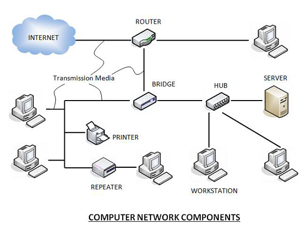
Basic elements of a computer network include hardware, software, and protocols. The interrelationship of these basic elements constitutes the infrastructure of the network. A network infrastructure is the topology in which the nodes of a local area network (LAN) or a wide area network (WAN) are connected to each other.
The following figure shows a network along with its components:
 .
.
Hardware Components
- Servers −Servers are high-configuration computers that manage the resources of the network. The network operating system is typically installed in the server and so they give user accesses to the network resources. Servers can be of various kinds: file servers, database servers, print servers etc.
- Clients − Clients are computers that request and receive service from the servers to access and use the network resources.
- Peers − Peers are computers that provide as well as receive services from other peers in a workgroup network.
- Transmission Media − Transmission media are the channels through which data is transferred from one device to another in a network. Transmission media may be guided media like coaxial cable, fibre optic cables etc; or maybe unguided media like microwaves, infra-red waves etc.
- Connecting Devices − Connecting devices act as middleware between networks or computers, by binding the network media together. Some of the common connecting devices are:
a. Routers
b. Bridges
c. Hubs
d. Repeaters
e. Gateways
f. Switches
Software Components
- Networking Operating System − Network Operating Systems is typically installed in the server and facilitate workstations in a network to share files, database, applications, printers etc.
- Protocol Suite − A protocol is a rule or guideline followed by each computer for data communication. Protocol suite is a set of related protocols that are laid down for computer networks. The two popular protocol suites are −
- a. OSI Model ( Open System Interconnections)
- b. TCP / IP Model
6.4. Describe the advantages of Computer network.
Main benefits of networks include:
6.5. Describe the application of computer network.
Every time you switch on your computer, you see a number of applications running on your computer. From the operating system to the small utilities, all are applications.
Computer networks support many applications and services, such as access to the World Wide Web, digital video, digital audio, shared use of application and storage servers, printers, and fax machines, and use of email and instant messaging applications.
The common networked applications are:
- E-mail: The email application uses SMTP and POP3 protocols to send and receive messages to/from an email server and email client. When you send an email message, the email client that you use sends the message to the email server using SMTP protocol. The email server reads the domain name of the destination email server and then sends the message to that server. If the server with the specified domain does not exist then the message is returned back to the email client. The message delivered to the email server is spooled or queued on the destination server. The destination server checks the queue and delivers the message to the destination email account. The email client uses POP3 protocol to download the message or receive the email.
- Remote login Telnet: The Telnet allows you to connect to a remote computer where you have an account. During a telnet session, your keyboard and mouse seem connected with the remote computer. A telnet client allows terminal emulation by logging into the telnet server. Once connected, telnet allows you to use remote computer resources as your local computer resources. The only problem with a telnet session is that, it sends username and password on the network in plain text.
- Network file system (NFS): NFS allows two different types of file systems to share files and interoperate on different computers on a Local Area Network (LAN). NFS allows data stored on network servers to be accessed by different types of client computers on the LAN. NFS is a distributed file system that is used in both UNIX based systems and other operating systems such as Mac OS, MS Windows, IBM and AS/400. If you want to access UNIX files from a Windows system then NFS allows you to access UNIX files by temporarily storing those files in RAM. Even after having different file naming restrictions, both types of users can access the same files in a normal manner.
- File Transfer between two accounts on two computers (FTP): The file transfer application uses FTP protocol to transfer files between two computers. The FTP uses an FTP client computer and an FTP server to operate. The client initiates the FTP process by accepting the username and password and creates an FTP session. During an FTP session, a client can upload and download files from the FTP server, change directories, and list files. Although you can upload and download files using HTTP protocol also, FTP is typically used for transferring large files and fast throughput.
- Domain Name Service (DNS): DNS resolves Fully Qualified Domain Name (FQDN) or host names to its IP address. It allows you to access websites by typing their user friendly names instead of remembering their IP address and typing it in a browser to access that website. The use of DNS allows you to change the IP address of a website as often as you want because it allows you to use domain names instead of IP address.
- Dynamic Host Configuration Protocol (DHCP): DHCP allows you to assign IP address to the host computers on your network dynamically. In the absence of DHCP, each computer on a network needs to be assigned a unique IP address manually. The manual assignment of IP addresses become a pain when a computer moves to a different network segment in a large network and needs to be assigned a different IP address. In large network environments the dynamic assignment of IP addresses eases the administrator’s task of managing IP addresses.
6.6. Describe client / server and peer-to-peer network.
Fig: client/server
- File server A computer that stores and manages files for multiple users on a network
- Web server A computer dedicated to responding to requests (from the browser client) for web pages
Fig : Peer-to-Peer network
6.7. Describe the general features of LAN, MANs and WANs
Local Area Networks (LAN):
Metropolitan-Area
Network (MAN)
WAN(Wide Area Network)
- A Wide Area Network is a network that extends over a large geographical area such as states or countries.
- A Wide Area Network is quite bigger network than the LAN.
- A Wide Area Network is not limited to a single location, but it spans over a large geographical area through a telephone line, fibre optic cable or satellite links.
7. Chapter 07.Understand the network topologies.
7.1 Define network topology.
7.2 Mention the difference between physical and logical topology.
7.3 Describe the physical connection of bus, ring, star, mesh and hybrid topologies.
7.4 Mention the advantages and disadvantages of bus, ring, star, mesh and hybrid topologies.
7.5 Describe the factors to select a particular topology.
7.6 Describe the logical topologies of a token ring network.
8
7.1. Define network topology.
A network topology is the pattern in which nodes (i.e., computers, printers, routers or other devices) are connected to a local area network (LAN) or other network via links (e.g., twisted pair copper wire cable or optical fiber cable). There are four principal topologies used in LANs: bus, tree, ring, and star .
7.2 Mention the difference between physical and logical topology.
Logical topology is the arrangement of devices on a computer network and how they communicate with one another.[1] Logical topologies describe how signals act on the network.[2]
In contrast, a physical topology defines how nodes in a network are physically linked and includes aspects such as geographic location of nodes and physical distances between nodes. The logical topology defines how nodes in a network communicate across its physical topology. The logical topology can be considered isomorphic to the physical topology, as vice versa.
Early twisted pair Ethernet with a single hub is a logical bus topology with a physical star topology. While token ring is a logical ring topology with a physical star topology.
(IN bangla
নেটওয়ার্ক টপোলজি (ইংরেজি: Network Topology) হলো এটি নেটওয়ার্কের ফিজিক্যাল ডিভাইস বা কম্পোনেন্ট। যেমন- ক্যাবল, পিসি, রাউটার ইত্যাদি যেভাবে নেটওয়ার্কে পরস্পরের সাথে সংযুক্ত থাকে তাকে বলা হয় টপোলজি। নেটওয়ার্ক টপোলজি মূলত নেটওয়ার্কের ফিজিক্যাল লেআউট (Layout) বর্ণনা করে থাকে। )
7.2. Describe the physical connection of bus, ring, star, mesh and hybrid topologies
Bus Topology
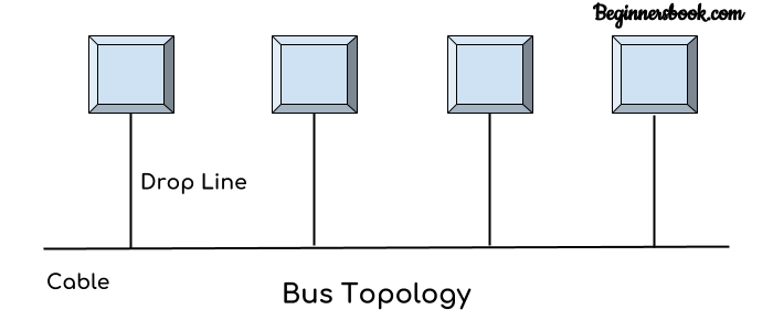
In bus topology there is a main cable and all the devices are connected to this main cable through drop lines. There is a device called tap that connects the drop line to the main cable. Since all the data is transmitted over the main cable, there is a limit of drop lines and the distance a main cable can have.
(IN Bangla:
বাস টপোলজির ক্ষেত্রে, সকল ডিভাইসগুলো ব্যাকবোন ক্যাবল হিসাবে পরিচিত একটি একক তারের মাধ্যমে সংযুক্ত থাকে। প্রতিটি নোড (একটি নেটওয়ার্কে সংযুক্ত প্রতিটি ডিভাইসকে নোড বলা হয়) ড্রপ ক্যাবল দ্বারা ব্যাকবোন তারের সাথে সংযুক্ত বা সরাসরি ব্যাকবোন তারের সাথে সংযুক্ত থাকে। যখন কোনও নোড নেটওয়ার্কের মাধ্যমে একটি বার্তা প্রেরণ করতে চায়, এটি নেটওয়ার্কে বার্তা পাঠায়। নেটওয়ার্কে সংযুক্ত সকল নোডগুলো বার্তাটি গ্রহণ করে। একাধিক হোস্ট একই সাথে ডেটা প্রেরণ করার সময় বাস টপোলজির সমস্যা হতে পারে। সুতরাং, বাস টপোলজি হয় CSMA/CD প্রযুক্তি ব্যবহার করে বা কোনও হোস্টকে সমস্যা সমাধানের জন্য বাস মাস্টার হিসাবে স্বীকৃতি দেয়। এটি নেটওয়ার্কিংয়ের একটি সহজ ফর্ম যেখানে একটি ডিভাইসের ব্যর্থতা অন্য ডিভাইসগুলোকে প্রভাবিত করে না। তবে শেয়ার করা ব্যাকবন লাইনের ব্যর্থতা অন্য সকল ডিভাইসগুলোর কাজ বন্ধ করে দিতে পারে।)
Ring Topology
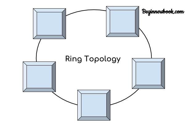
In ring topology each device is connected with the two devices on either side of it. There are two dedicated point to point links a device has with the devices on the either side of it. This structure forms a ring thus it is known as ring topology. If a device wants to send data to another device then it sends the data in one direction, each device in ring topology has a repeater, if the received data is intended for other device then repeater forwards this data until the intended device receives it.
(রিং টপোলজিতে প্রতিটি কম্পিউটার বা নোড ক্যাবলের সাহায্যে তার পার্শ্ববর্তী দুটি কম্পিউটারের সাথে সরাসরি সংযুক্ত হয়ে একটি লুপ বা রিং গঠন করে। এভাবে রিংয়ের সর্বশেষ কম্পিউটার প্রথমটির সাথে যুক্ত হয়। এই টপোলজিতে সিগন্যাল একটি নির্দিষ্ট দিকে ট্রান্সমিশন হয়। টপোলজির প্রতিটি ডিভিাইসে একটি রিসিভার এবং একটি ট্রান্সমিটার থাকে যা রিপিটারের কাজ করে। এক্ষেত্রে রিপিটারের দায়িত্ব হচ্ছে সিগন্যাল একটি কম্পিউটার থেকে তার পরের কম্পিউটারে পৌছেঁ দেওয়া। নেটওয়ার্কের কোনো একটি কম্পিউটার সংকেত পুনঃপ্রেরণের ক্ষমতা হারালে কিংবা কম্পিউটারটি নষ্ট হয়ে গেলে পুরো নেটওয়ার্কটি অকেজো হয়ে যায়। তখন নষ্ট কম্পিউটারটি অপসারণ করে পুনরায় সংযোগ সম্পন্ন করতে হয়।)
Star Topology
(রিং টপোলজিতে প্রতিটি কম্পিউটার বা নোড ক্যাবলের সাহায্যে তার পার্শ্ববর্তী দুটি কম্পিউটারের সাথে সরাসরি সংযুক্ত হয়ে একটি লুপ বা রিং গঠন করে। এভাবে রিংয়ের সর্বশেষ কম্পিউটার প্রথমটির সাথে যুক্ত হয়। এই টপোলজিতে সিগন্যাল একটি নির্দিষ্ট দিকে ট্রান্সমিশন হয়। টপোলজির প্রতিটি ডিভিাইসে একটি রিসিভার এবং একটি ট্রান্সমিটার থাকে যা রিপিটারের কাজ করে। এক্ষেত্রে রিপিটারের দায়িত্ব হচ্ছে সিগন্যাল একটি কম্পিউটার থেকে তার পরের কম্পিউটারে পৌছেঁ দেওয়া। নেটওয়ার্কের কোনো একটি কম্পিউটার সংকেত পুনঃপ্রেরণের ক্ষমতা হারালে কিংবা কম্পিউটারটি নষ্ট হয়ে গেলে পুরো নেটওয়ার্কটি অকেজো হয়ে যায়। তখন নষ্ট কম্পিউটারটি অপসারণ করে পুনরায় সংযোগ সম্পন্ন করতে হয়।)
Mesh Topology
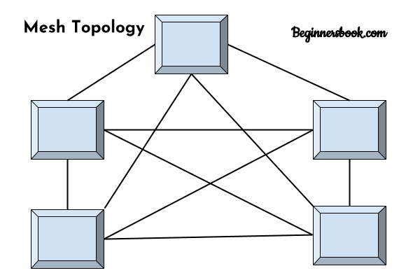
In mesh topology each device is connected to every other device on the network through a dedicated point-to-point link. When we say dedicated it means that the link only carries data for the two connected devices only. Lets say we have n devices in the network then each device must be connected with (n-1) devices of the network. Number of links in a mesh topology of n devices would be n(n-1)/2.
Hybrid topology
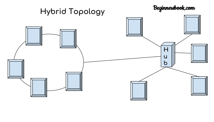
A combination of two or more topology is known as hybrid topology. For example a combination of star and mesh topology is known as hybrid topology.
(ভিন্ন ধরণের একাধিক টপোলজির সমন্বয়ে যদি নতুন এক ধরণের টপোলজি গঠিত হয় তখন নতুন টপোলজিটিকে হাইব্রিড টপোলজি বলা হয়। উদাহরণস্বরূপ, রুপালী ব্যাংকের একটি শাখায় যদি রিং টপোলজি এবং রুপালী ব্যাংকের অন্য শাখায় বাস টপোলজির উপস্থিতি থাকে তবে এই দুটি টপোলজিকে সংযুক্ত করার ফলে হাইব্রিড টপোলজি গঠিত হবে।
ইন্টারনেটকে হাইব্রিড টপোলজি হিসেবে অভিহিত করা যায়। ইন্টারনেট একটি হাইব্রিড নেটওয়ার্ক, কেননা ইন্টারনেট হলো বৃহৎ পরিসরের একটি নেটওয়ার্ক যেখানে সব ধরনের টপোলজির মিশ্রণ দেখা যায়।
)
7.3. Mention the advantages and disadvantages of bus, ring, star, mesh and hybrid topologies.
1.Advantages of bus topology
1. Easy installation, each cable needs to be connected with backbone cable.
2. Less cables required than Mesh and star topology
Disadvantages of bus topology
1. Difficultly in fault detection.
2. Not scalable as there is a limit of how many nodes you can connect with backbone cable.
2.Advantages of Ring Topology
1. Easy to install.
2. Managing is easier as to add or remove a device from the topology only two links are required to be changed.
Disadvantages of Ring Topology
1. A link failure can fail the entire network as the signal will not travel forward due to failure.
2. Data traffic issues, since all the data is circulating in a ring.
3. Advantages of Star topology
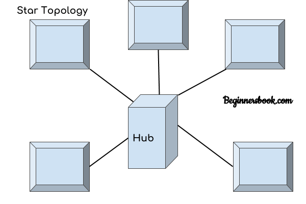
1. Less expensive because each device only need one I/O port and needs to be connected with hub with one link.
2. Easier to install
3. Less amount of cables required because each device needs to be connected with the hub only.
4. Easy fault detection because the link can be easily identified.
Disadvantages of Star topology
1. If hub goes down everything goes down, none of the devices can work without hub.
2. Hub requires more resources and regular maintenance because it is the central system of star topology.
4. Advantages of Mesh topology
1. No data traffic issues as there is a dedicated link between two devices which means the link is only available for those two devices.
2. Mesh topology is secure because there is a point to point link thus unauthorized access is not possible.
3. Fault detection is easy.
Disadvantages of Mesh topology
1. Amount of wires required to connected each system is tedious and headache.
2. Since each device needs to be connected with other devices, number of I/O ports required must be huge.
5. Advantages of Hybrid topology
1. We can choose the topology based on the requirement for example, scalability is our concern then we can use star topology instead of bus technology.
2. Scalable as we can further connect other computer networks with the existing networks with different topologies.
Disadvantages of Hybrid topology
1. Fault detection is difficult.
2. Installation is difficult.
3. Design is complex so maintenance is high thus expensive.
১। বাস টপোলজি ব্যবহারের সুবিধাসমূহ:
১। এই টপোলজির প্রধান সুবিধা হলো নেটওয়ার্ক খুব সাধারণ এবং ফিজিক্যাল লাইনের সংখ্যা মাত্র একটি।
২। এই টপোলজি সরল এবং ছোট আকারের নেটওয়ার্কে ব্যবহার করা সহজ।
৩। বাস টপোলজির কোনো একটি নোড নষ্ট হলেও অন্য নোডগুলো প্রভাবিত হয় না।
৪। বাস টপোলজিতে কম তারের প্রয়োজন হয় এবং হাব বা সুইচের মত কোন নেটওয়ার্কিং ডিভাইসের প্রয়োজন হয় না ফলে খরচ কম হয়।
বাস টপোলজি ব্যবহারের অসুবিধাসমূহঃ
১। মূল ক্যাবল বা ব্যাকবোন নষ্ট হয়ে গেলে সম্পূর্ণ নেটওয়ার্ক সিস্টেম অচল হয়ে যায়।
২। এই টপোলজিতে ডেটা ট্রান্সমিশনের জন্য কোনো সমন্বয়ের ব্যবস্থা নেই। যেকোনো নোড যেকোনো সময়ে ডেটা ট্রান্সমিশন করতে পারে। যদি দুটি নোড একই সাথে বার্তা পাঠায় তবে উভয় নোডের সংকেত একে অপরের সাথে সংঘর্ষ হয়।
৩। যদি নেটওয়ার্কের ট্রাফিক বৃদ্ধি পায় তাহলে নেটওয়ার্কের ডেটা কলিশন বৃদ্ধি পায়।
৪। নেটওয়ার্কে কম্পিউটার সংখ্যা বেশি হলে ডেটা ট্রান্সমিশন বিঘ্নিত হয়।
৫। বাস টপোলজিতে সৃষ্ট সমস্যা নির্ণয় তুলনামূলক বেশ জটিল।
২.রিং টপোলজি ব্যবহারের সুবিধাসমূহ:
১। নেটওয়ার্কে কোনো সার্ভার কম্পিউটারের প্রয়োজন হয় না। ২। নেটওয়ার্কে কম্পিউটার সংখ্যা বাড়লেও এর দক্ষতা খুব বেশি প্রভাবিত হয় না। ৩। এটি নির্ভরযোগ্য কারণ যোগাযোগ ব্যবস্থাটি একক হোস্ট কম্পিউটারের উপর নির্ভর করে না। ৪। এই টপোলজিতে সংঘর্ষের সম্ভাবনা সর্বনিম্ন।রিং টপোলজি ব্যবহারের অসুবিধাসমূহ:
১। নেটওয়ার্কের একটি মাত্র কম্পিউটার নষ্ট হলে পুরো নেটওয়ার্ক অচল হয়ে যায়। ২। রিং টপোলজির ক্ষেত্রে নেটওয়ার্কের কোনো সমস্যা নিরুপণ বেশ জটিল। ৩। নেটওয়ার্কে কোনো কম্পিউটার যোগ করলে বা অপসারণ করলে তা পুরো নেটওয়ার্কের কার্যক্রম ব্যহত করে।৩। স্টার টপোলজির সুবিধাসমূহ:
১। এই টপোলজিতে কোনো একটি নোড নষ্ট হলে নেটওয়ার্কের বাকি নোডগুলো প্রভাবিত হয় না। ২। এই টপোলজিতে টুইস্টেড পেয়ার, কো-এক্সিয়াল ও ফাইবার অপটিক ক্যাবল ব্যবহার করা যায়। ৩। যেকোন সময় নোড যোগ করা বা বাদ দেওয়া যায়, এতে নেটওয়ার্ক প্রভাবিত হয় না। ৪। ডেটা চলাচলের গতি বেশি।স্টার টপোলজির অসুবিধাসমূহ:
১। এই টপোলজিতে কেন্দ্রীয় ডিভাইসটি(হাব বা সুইচ) নষ্ট হয়ে গেলে সম্পূর্ণ নেটওয়ার্ক সিস্টেমই অচল হয়ে যায়। ২। স্টার টপোলজিতে প্রচুর পরিমাণে ক্যাবল এবং কেন্দ্রীয় ডিভাইস ব্যবহৃত হয় বিধায় এটি ব্যয়বহুল। ৩। নেটওয়ার্কের কার্যক্ষমতা কেন্দ্রীয় ডিভাইসের উপর নির্ভর করে।
৪। মেশ টপোলজি ব্যবহারের সুবিধাসমূহ:
১। যেকোনো দুটি নোডের মধ্যে অত্যন্ত দ্রুতগতিতে ডেটা আদান-প্রদান করা যায়। ২। একটি সংযোগ লাইন নষ্ট হয়ে গেলেও বিকল্প সংযোগ লাইন ব্যবহার করে ডেটা আদান-প্রদান করা যায়। ৩। এতে ডেটা কমিউনিকেশনে অনেক বেশি নিশ্চয়তা থাকে। ৪। নেটওয়ার্কের সমস্যা খুব সহজে সমাধান করা যায়। ৫। নিরাপত্তা এবং গোপনীয়তা রক্ষা করে।মেশ টপোলজি ব্যবহারের অসুবিধাসমূহ:
১। এই টপোলজিতে নেটওয়ার্ক ইনস্টলেশন ও কনফিগারেশন বেশ জটিল। ২। নেটওয়ার্কে অতিরিক্ত লিংক স্থাপন করতে হয় বিধায় এতে খরচ বেড়ে যায়।৫। হাইব্রিড টপোলজি ব্যবহারের সুবিধা:
১। এই টপোলজিতে প্রয়োজন অনুযায়ী নেটওয়ার্ক বৃদ্ধি করার সুযোগ রয়েছে। ২। কোনো একটি অংশ নষ্ট হয়ে গেলে সম্পূর্ণ নেটওয়ার্ক অচল হয় না।হাইব্রিড টপোলজি ব্যবহারের অসুবিধা:
১। হাইব্রিড টপোলজির বড় অসুবিধা হলো হাইব্রিড নেটওয়ার্কের নকশা বা ডিজাইন করা। হাইব্রিড নেটওয়ার্কের আর্কিটেকচার ডিজাইন করা খুব কঠিন। ২। হাইব্রিড টপোলজিতে ব্যবহৃত হাবগুলো খুব ব্যয়বহুল। কারণ এই হাবগুলো অন্যান্য টপোলজিতে ব্যবহৃত স্বাভাবিক হাবের চেয়ে পৃথক। ৩। হাইব্রিড নেটওয়ার্কে প্রচুর ক্যাবলিং, নেটওয়ার্ক ডিভাইস ইত্যাদির প্রয়োজন হওয়ায় কাঠামোর ব্যয় খুব বেশি।
7.4. the key factors you should pay attention to when choosing a network topology.
Network topology refers to the physical configuration of a set of interconnected computing devices. It details not just how devices on the network are connected but also how data moves from one node to another.
The following are the key factors you should pay attention to when choosing a network topology.
1. Budget
A rule of thumb is to never make technology procurement decisions based on price alone. There’s no denying though that you can only cut your coat according to your cloth. If a topology is unaffordable, it’s off the table no matter how perfectly suited it might be for your situation.
In any case, irrespective of what your preferred topology is, there’ll almost always be a lower-priced alternative that’s nearly as effective. On pricing matters, bus and ring topologies are quite cost-effective while star, mesh, tree and hybrid topologies are expensive.
2. Hardware Resources
Certain network topologies work best with certain hardware. And vise-versa. So before you make a decision on the topology to adopt, perform an inventory of your current hardware. You may also already have the hardware needed to implement a certain type of topology. So as opposed to buying everything from scratch, such existing resources give you a head start.
For instance, you may have hardware limitations such as the length of the network cable. In that case, you’d go for a topology that requires the least amount of cable for connecting nodes. Bus and star topologies perform pretty well in this regard.
3. Ease of Implementation
If you’ll contract a third party to install and/or maintain your network, then the complexity of the network topology you choose is perhaps a non-issue. A competent networking professional will have the education and experience needed to comprehend what each topology entails and implement it accordingly.
However, if you expect to leave network implementation in the hands of novices or individuals without the requisite IT training, then the ease of the topology should be a major factor in your choice. In this case, the bus and star topologies score pretty well. The mesh, tree and hybrid, on the other hand, are complex and difficult for a layman to install or understand.
4. Size of Network
How many devices are going to be on your network? How geographically dispersed are they? How far from the ‘center’ is the furthest device? Some topologies are inadequate or expensive when applied to large networks. A topology that works perfectly for a 5-device network may prove a disaster when applied to a 10,000-device organization.
Part of the inventorying process we referred to in point 2 should include determining the total number of devices to be interconnected. Armed with this information, you can choose the topology that would best serve the purpose. The tree topology works well with large networks. The bus topology is best suited for small organizations.
5. Reliability
When it comes to reliability, network topologies aren’t created equal. If you are looking for high reliability because you are in an industry where even brief downtime and delays are frowned upon (e.g. banking), then network reliability is a fundamental consideration. Choose the topology that delivers the highest reliability.
Ring topology performs pretty well under heavy loads but is prone to a single point of failure. Star topology doesn’t depend on any node but the network will collapse if the hub fails. Mesh and hybrid topologies score highest on the reliability front.
6. Future Expansion
If you expect your organization to grow in size in the medium to long-term, opt for a network topology that’s readily scalable. Identify the topology that’s easy to add new nodes to, without negatively affecting network performance or the user experience of other devices on the network.
The tree topology is perhaps the most compatible with future expansion requirements as it’s fairly easy to extend or shrink the network. The bus topology is also easy to expand but only to a certain extent which is why it would only work for small networks.
Choosing a network topology is one of the most important decisions you’ll make for your technology infrastructure and will have far-reaching ramifications over the long-term. A wrong choice can prove to be an expensive mistake.
7.5. Describe the logical topologies of a token ring network.
the logical topologies of a token ring network.A token ring network is a local area network (LAN) in which all computers are connected in a ring or star topology and pass one or more logical tokens from host to host. Only a host that holds a token can send data, and tokens are released when receipt of the data is confirmed.
(
টোকেন রিং কীভাবে কাজ করে
টোকেন রিং নেটওয়ার্ক কম্পিউটার গুলি ফিজিক্যাল স্টার টপোলজিতে MSAU এর সাথে যুক্ত থাকলেও এটি কাজ করে রিং আকারে। এক্ষেত্রে নেটওয়ার্ক একসেস মেথড হিসেবে টোকেন পাসিং ব্যবহার করা হয়। মতো একটি বিশেষ ফরম্যাট ফ্রেম, যা টোকেন নামে পরিচিত, একই দিকে ঘুরতে পারে। কোনাে নােড় এহতেশ পায় তার কাছের প্রতিবেশী নিজের কাছ থেকে। সে এই টোকেন পাওয়ার পর এটিকে পাঠায় পরবতা প্রতিরাের! নিকট। এভাবে টোকেনটি বলয়ে ঘুর্ণায়মান থাকে। কোনাে নােডের ডাটা ট্রান্সমিট করার দরকার হলে সে ওহ টোকেন তার হাতে না আসা পর্যন্ত অপেক্ষা করবে। টোকেন হাতে আসলে সে ওই টোকেন ফ্রেমের সাথে ভাটাকে যুক্ত করে এবং সেটি পরবর্তী নােডের নিকট পাঠায়। সেই নােড দেখে ওই প্যাকেট তার জন্য কি না। তার জন্য না হলে সে পাঠায় তার পরবর্তী নােডের নিকট। এভাবে সেটি বলয়ে ঘুরতে থাকে। যখন গন্তব্য নােডে সেই প্যাকেট পৌঁছে তখন সে ওটির একটি কপি রেখে দেয়। তার নিকট প্যাকেট পৌঁছেছে এটি যাতে প্রেরণকারী নােড বুঝতে পারে সেজন্য গ্রহণকারী নােড দুই বিটের ফ্রেম পাঠায়। সেটি প্রেরণকারী নােডের নিকট পৌঁছুলে সে বুঝতে পারে যে তার পাঠানো প্যাকেট গন্তব্যে পৌঁছেছে। দুই বিটের ফ্রেম পাঠানোর পর গ্রহণকারী নােড টোকেন ও ডাটাকে ভিন্ন করে ফেলে এবং ডাটা উপরের লেয়ারগুলোর নিকট পাঠিয়ে। টোকেন সহ ডাটাফ্রেম আবার রিঙে ঘুরে প্রেরণকারী নােডে পৌছে।
একটি নােডের নিকট কতক্ষণ পরপর টোকেন যাবে, সে কতক্ষণ ওই টোকেন নিজের দখলে রাখতে পারবে তার। সুনির্দিষ্ট নিয়ম আছে। এর ফলে কোনাে নােড একচ্ছত্র আধিপত্য বিস্তার করতে পারে না। টোকেন রিং নেটওয়ার্ক তাই ইকুয়াল একসেস নেটওয়ার্ক বলে পরিচিত।
)8. Definition of Protocol (Chapter 8)
8. Understand network protocols.
8.1 Define network protocol.
8.2 Describe the main elements of protocol.
8.3 Describe the characteristics of protocol.
8.4 Describe the functions of protocol.
8.5 List different types of network protocols.
8.6 State the function of TCP/IP protocol.
8.1 Definition of Protocol
Protocol. A protocol is a standard set of rules that allow electronic devices to communicate with each other. These rules include what type of data may be transmitted, what commands are used to send and receive data, and how data transfers are confirmed.
(
প্রোটোকল কি
যে পদ্ধতির মাধ্যমে কমিউনিকেশন সিস্টেমে কম্পিউটার এবং বিভিন্ন ডিভাইস বা ডেটা ট্রান্সমিট পদ্ধতি সফটওয়্যারের মাধ্যমে নিয়ন্ত্রণ করা হয় তাকে প্রোটোকল বলে। বিভিন্ন প্রতিষ্ঠান বিভিন্ন ধরণের প্রোটোকল তৈরি করেছে। যেমনঃ FTP (File Transferr Protocol), NETBUEI, AppleTalk,TCP/IP ইত্যাদি। এদের মধ্যে ইন্টারনেট ব্যবহৃত প্রোটোকল হচ্ছে TCP/IP (Transmission Control Protocol / Internet Protocol). )
8.2 Describe the main elements of protocol.
The key elements of a protocol are syntax, semantics, and timing.
Key Elements of Protocol
- Syntax,
- Semantics, and
- Timing.
1. Syntax
The term syntax refers to the structure or format of the data, meaning the order in which they are presented.
For example, a simple protocol might expect the first 8 bits of data to be the address of the sender, the second 8 bits to be the address of the receiver, and the rest of the stream to be the message itself.
2. Semantics
The word semantics refers to the meaning of each section of bits. How is a particular pattern to be interpreted, and what action is to be taken based on that interpretation?
For example, does an address identify the route to be taken or the final destination of the message?
3. Timing
The term timing refers to two characteristics: when data should be sent and how fast they can be sent.
For example, if a sender produces data at 100 Mbps but the receiver can process data at only 1 Mbps, the transmission will overload the receiver and some data will be lost.
8.3 DESCRIBE THE CHARACTERISTICS OF PROTOCOL.
Some important characteristics of a protocol are as follows
- Direct/indirect
- Monolithic/structured
- Symmetric/asymmetric
- Standard/nonstandard

8.4 DESCRIBE THE FUNCTIONS OF PROTOCOL.
We can group protocal functions into the following categories
- Encapsulation
- Segmentation and reassembly
- Conncetion Control
- Ordered delivery
- Flow control
- Error control
- Addressing
- Multiplexing
- Transmission
8.5
List different types of network protocols.
There are various types of protocols that support a major and compassionate role in communicating with different devices across the network. These are:
1. Transmission Control Protocol (TCP)
2. Internet Protocol (IP)
3. User Datagram Protocol (UDP)
4. Post office Protocol (POP)
5. Simple mail transport Protocol (SMTP)
6. File Transfer Protocol (FTP)
7. Hyper Text Transfer Protocol (HTTP)
8. Hyper Text Transfer Protocol Secure (HTTPS)
9. Telnet
10. Gopher
Let's discuss each of them briefly:
1. Transmission Control Protocol (TCP): TCP is a popular communication protocol which is used for communicating over a network. It divides any message into series of packets that are sent from source to destination and there it gets reassembled at the destination.
2. Internet Protocol (IP): IP is designed explicitly as addressing protocol. It is mostly used with TCP. The IP addresses in packets help in routing them through different nodes in a network until it reaches the destination system. TCP/IP is the most popular protocol connecting the networks.
3. User Datagram Protocol (UDP): UDP is a substitute communication protocol to Transmission Control Protocol implemented primarily for creating loss-tolerating and low-latency linking between different applications.
4. Post office Protocol (POP): POP3 is designed for receiving incoming E-mails.
5. Simple mail transport Protocol (SMTP): SMTP is designed to send and distribute outgoing E-Mail.
6. File Transfer Protocol (FTP): FTP allows users to transfer files from one machine to another. Types of files may include program files, multimedia files, text files, and documents, etc.
7. Hyper Text Transfer Protocol (HTTP): HTTP is designed for transferring a hypertext among two or more systems. HTML tags are used for creating links. These links may be in any form like text or images. HTTP is designed on Client-server principles which allow a client system for establishing a connection with the server machine for making a request. The server acknowledges the request initiated by the client and responds accordingly.
8. Hyper Text Transfer Protocol Secure (HTTPS): HTTPS is abbreviated as Hyper Text Transfer Protocol Secure is a standard protocol to secure the communication among two computers one using the browser and other fetching data from web server. HTTP is used for transferring data between the client browser (request) and the web server (response) in the hypertext format, same in case of HTTPS except that the transferring of data is done in an encrypted format. So it can be said that https thwart hackers from interpretation or modification of data throughout the transfer of packets.
9. Telnet: Telnet is a set of rules designed for connecting one system with another. The connecting process here is termed as remote login. The system which requests for connection is the local computer, and the system which accepts the connection is the remote computer.
10. Gopher: Gopher is a collection of rules implemented for searching, retrieving as well as displaying documents from isolated sites. Gopher also works on the client/server principle.
8.6 State the function of TCP/IP protocol.
TCP/IP, or the Transmission Control Protocol/Internet Protocol, is a suite of communication protocols used to interconnect network devices on the internet. TCP/IP can also be used as a communications protocol in a private computer network
The two main protocols in the Internet Protocol suite serve specific functions. TCP defines how applications can create channels of communication across a network. It also manages how a message is assembled into smaller packets before they are then transmitted over the internet and reassembled in the right order at the destination address.
IP defines how to address and route each packet to make sure it reaches the right destination. Each gateway computer on the network checks this IP address to determine where to forward the message.
TCP/IP functionality is divided into four layers, each of which include specific protocols:
- The application layer provides applications with standardized data exchange. Its protocols include the HTTP, FTP, Post Office Protocol 3 (POP3), Simple Mail Transfer Protocol (SMTP) and Simple Network Management Protocol (SNMP). At the application layer, the payload is the actual application data.
- The transport layer is responsible for maintaining end-to-end communications across the network. TCP handles communications between hosts and provides flow control, multiplexing and reliability. The transport protocols include TCP and User Datagram Protocol (UDP), which is sometimes used instead of TCP for special purposes.
- The network layer, also called the internet layer, deals with packets and connects independent networks to transport the packets across network boundaries. The network layer protocols are the IP and the Internet Control Message Protocol (ICMP), which is used for error reporting.
- The physical layer, also known as the network interface layer or data link layer, consists of protocols that operate only on a link -- the network component that interconnects nodes or hosts in the network. The protocols in this lowest layer include Ethernet for local area networks (LANs) and the Address Resolution Protocol (ARP).
(
TCP/IP
টিসিপি/আইপি হলো ইন্টারনেট ব্যবহারের জন্য প্রটোকল স্যুট । এই প্রটোকল স্যুটে দুটি প্রটোকলের নাম দেওয়া হয়েছে। এই প্রটোকল দুটি হলো : ট্রান্সমিশন কন্ট্রোল প্রটোকল (TCP) ও ইন্টারনেট প্রটোকল (IP)। TCP ব্যবহৃত হয় কানেকশন-অরিয়েন্টেড নির্ভরযোগ্য ট্রান্সমিশন সার্ভিসের জন্য, আর IP ব্যবহৃত হয় ওই নেটওয়ার্কের প্রতিটি হোস্টের এড্রেস নির্ধারণের জন্য।
টিসিপি কি?
টিসিপি হলো ট্রান্সমিশন কন্ট্রোল প্রটোকল । ইহা কানেকশন ওরিয়েন্টেড একটি একুনলেজ সিগন্যাল এর মাধ্যাম কানেকশন তৈরি করে থাকে।
টিসিপি হলো ট্রান্সমিশন কন্ট্রোল প্রটোকল । ইহা কানেকশন ওরিয়েন্টেড একটি একুনলেজ সিগন্যাল এর মাধ্যাম কানেকশন তৈরি করে থাকে।
টিসিপি/আইপি হলো ইন্টারনেট ব্যবহারের জন্য প্রটোকল স্যুট । এই প্রটোকল স্যুটে দুটি প্রটোকলের নাম দেওয়া হয়েছে। এই প্রটোকল দুটি হলো : ট্রান্সমিশন কন্ট্রোল প্রটোকল (TCP) ও ইন্টারনেট প্রটোকল (IP)। TCP ব্যবহৃত হয় কানেকশন-অরিয়েন্টেড নির্ভরযোগ্য ট্রান্সমিশন সার্ভিসের জন্য, আর IP ব্যবহৃত হয় ওই নেটওয়ার্কের প্রতিটি হোস্টের এড্রেস নির্ধারণের জন্য।
9. Understand IP addressing. (chapter 9)
9.1 Define Network Addressing.
9.2 Define IP and IPv4
9.3 Describe the IP address formats of class A,B,C,D &E with example.
9.4 Describe subnet and subnet masks.
9.5 State CIDR format of subnet.
9.6 Define IPv6.
9.7 Describe the address format of IPv6.
9.1 Define Network Addressing.
A network address is an identifier for a node or host on a telecommunications network. Network addresses are designed to be unique identifiers across the network, although some networks allow for local, private addresses, or locally administered addresses that may not be unique.
9.2 Define IP and IPv4
IP Address
IPV4 address
The IPv4 address is a 32-bit number that uniquely identifies a network interface on a machine. An IPv4 address is typically written in decimal digits, formatted as four 8-bit fields that are separated by periods. Each 8-bit field represents a byte of the IPv4 address. This form of representing the bytes of an IPv4 address is often referred to as the dotted-decimal format.
The bytes of the IPv4 address are further classified into two parts: the network part and the host part. The following figure shows the component parts of a typical IPv4 address, 129.144.50.56.
Figure 5–3 Parts of an IPv4 Address

Network Part
The network part specifies the unique number that is assigned to your network. The network part also identifies the class of network that is assigned. In Figure 5–3, the network part occupies two bytes of the IPv4 address.
Host Part
This is the part of the IPv4 address that you assign to each host. The host part uniquely identifies this machine on your network. Note that for each host on your network, the network part of the address is the same, but the host part must be different.
9.3 Describe the IP address formats of class A,B,C,D &E with example.
The first bit of the first octet is always set to zero. So that the first octet ranges from 1 – 127. The class A address only include IP starting from 1.x.x.x to 126.x.x.x. The IP range 127.x.x.x is reserved for loop back IP addresses. The default subnet mask for class A IP address is 255.0.0.0. This means it can have 126 networks (27-2) and 16777214 hosts (224-2).
Class A IP address format is thus: 0NNNNNNN.HHHHHHHH.HHHHHHHH.HHHHHHHH.
Here the first two bits in the first two bits is set to zero. Class B IP Addresses range from 128.0.x.x to 191.255.x.x. The default subnet mask for Class B is 255.255.x.x. Class B has 16384 (214) Network addresses and 65534 (216-2) Host addresses. Class B IP address format is: 10NNNNNN.NNNNNNNN.HHHHHHHH.HHHHHHHH
Class C Address
The first octet of this class has its first 3 bits set to 110. Class C IP addresses range from 192.0.0.x to 223.255.255.x. The default subnet mask for Class C is 255.255.255.x. Class C gives 2097152 (221) Network addresses and 254 (28-2) Host addresses. Class C IP address format is: 110NNNNN.NNNNNNNN.NNNNNNNN.HHHHHHHH
The first four bits of the first octet in class D IP address are set to 1110. Class D has IP address rage from 224.0.0.0 to 239.255.255.255. Class D is reserved for Multicasting. In multicasting data is not intended for a particular host, but multiple ones. That is why there is no need to extract host address from the class D IP addresses. The Class D does not have any subnet mask.
The class E IP addresses are reserved for experimental purpose only for R&D or study. IP addresses in the class E ranges from 240.0.0.0 to 255.255.255.254. This class too is not equipped with any subnet mask.
9.4 Describe subnet and subnet masks.
SUBNET
A subnetwork or subnet is a logical subdivision of an IP network. The practice of dividing a network into two or more networks is called subnetting. Computers that belong to a subnet are addressed with an identical most-significant bit-group in their IP addresses.
SUBNET MASKS.
An IP address has two components, the network address and the host address. A subnet mask separates the IP address into the network and host addresses (<network><host>).
10. Understand Network Interface Cards (NIC) (chapter 10)
10.1 State the role of NIC.
10.2 Describe the format of Physical address (MAC Address) of NIC.
10.3 Mention the points that agree both the sending and receiving NICs.
10.4 State the importance of base memory address for NIC.
10.5 Mention the important points to maintain the compatibility among NIC, bus and cables.
10.6 Describe the NIC related factors that enhanced the performance of network.
10.1 State the role of NIC.
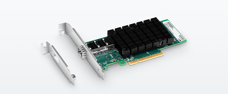
Before introducing the NIC definition, it's necessary to know there are quite a few names for the network interface card based on habits in different regions, such as network interface controller, Ethernet card, LAN card, network adapter or network adapter card (NAC). It seems a little bit confusing, but no matter what names the NIC has, they all refer to the circuit board that enables devices like computers and network servers to be connected over a network. Currently, the NIC card designed as a built-in style is commonly found in most computers and some network servers. Besides, network cards like server network card can also be inserted into expansion slots of devices.
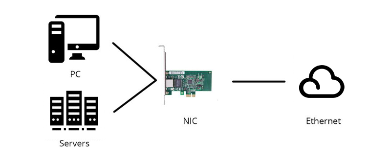
NIC definition is very simple, but what does a network interface card do and what is the function of NIC? Working as an interface at the TCP/IP layer, a NIC card can transmit signals at the physical layer and deliver data packets at the network layer. No matter what layer the network interface controller lies, it acts as a middleman between a computer/server and a data network. When a user requests a web page, the LAN card gets data from the user device, and sends them to the server on the internet, then receives the required data back from the Internet to display for users.Function of NIC
10.2
Describe the format of Physical address (MAC Address) of NIC.
What is a MAC address?
A MAC (Media Access Control) address is the hardware address of the Network Interface Card (NIC) of your computer. You must have it on hand to register for the UCInet Mobile Access network and campus-wide DHCP services. This Web page will help you locate and identify it so you may register your Network Interface Card (or cards) for the network.
Media Access Control (MAC) Addressing
The MAC address is the unique serial number burned into each network adapter that differentiates the network card from all others, just as your house number is unique on your street and identifies your home from all others. To be a part of any network, you must have an address so that others can reach you. Two types of addresses are found in a network: the logical (OSI model Layer 3, network) and the physical (OSI model Layer 2, data link). For this discussion of LAN environments, the physical address (also known as the Media Access Control [MAC] address) is relevant.
A MAC address is the physical address of the device. It is 48 bits (6 bytes) long and is made up of two parts: the organizational unique identifier (OUI) and the vendor-assigned address, as illustrated in Figure 5.1.
Figure 5-1. MAC Address
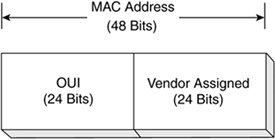
The MAC address on a computer might look like this: 00-08-a1-08-c8-13. This MAC address is used for the Fast Ethernet adapter on the computer in question. The OUI is 00-08-a1, and the vendor-assigned number is 08-c8-13.
The OUI is administered by the IEEE and identifies the vendor of the network adapter. The vendor-assigned portion of the MAC address is just that, the alphanumeric identifier assigned by the vendor. It is the combination of the OUI and the vendor-assigned number that ensures that no two network adapters have the same MAC address.
Finding Your MAC Address
Windows (two methods)
Method 1:
- Click Start and in the Search Programs and Files box type ncpa.cpl and then push Enter on your keyboard.
- The Network Connections window will appear. Double-click on either Local Area Connection icon (if you are trying to register your Ethernet/wired connection) or Wireless Network Connection.
- In the window that appears, click Details… and in the subsequent window you’ll see the Physical Address field: that is your MAC address.
Method 2:
- Click Start then Run (in Windows 7, Start and type in the Search Programs and Files box.)
- Enter: cmd
- Enter: ipconfig /all
If the output scrolls off your screen, and it will on Vista and Windows 7, use: ipconfig /all | more - The Physical Address is your MAC address; it will look like 00-15-E9-2B-99-3C. You will have a physical address for each network connection that you have.

11. Understand the connectivity devices (chaptere 11)
11.1 List the connectivity devices used in networking.
11.2 Describe function of MODEM.
11.3 Describe MODEM types and Standard.
11.4 Describe the features of ADSL and Digital MODEM.
11.5 Describe the functions of Hubs, Repeaters and switches in network.
11.6 Describe the important features of Repeaters and switches.
11.7 Describe the functions of Router and Gateway
11.1 List the connectivity devices used in networking.
- The Network Interface card (NIC)
- The hub.
- The switch.
- The bridge.
- Transceivers.
- Wireless access points.
- The router.
- The gateway.
Hub
When referring to a network, a hub is the most basic networking device that connects multiple computers or other network devices together. Unlike a network switch or router, a network hub has no routing tables or intelligence on where to send information and broadcasts all network data across each connection. Most hubs can detect basic network errors such as collisions, but having all information broadcast to multiple ports can be a security risk and cause bottlenecks. In the past, network hubs were popular because they were cheaper than a switch or router. Today, switches do not cost much more than a hub and are a much better solution for any network.

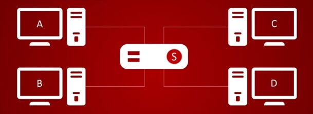
A hub is to sent out a message from one port to other ports. For example, if there are three computers of A, B, C, the message sent by a hub for computer A will also come to the other computers. But only computer A will respond and the response will also go out to every other port on the hub. Therefore, all the computers can receive the message and computers themselves need to decide whether to accept the message.
Switch
A switch is able to handle the data and knows the specific addresses to send the message. It can decide which computer is the message intended for and send the message directly to the right computer. The efficiency of switch has been greatly improved, thus providing a faster network speed.
Router
Router is actually a small computer that can be programmed to handle and route the network traffic. It usually connects at least two networks together, such as two LANs, two WANs or a LAN and its ISP network. Routers can calculate the best route for sending data and communicate with each other by protocols.

What Is the Difference?
11.2 Describe function of MODEM.
A MODEM is a Modulator-Demodulator. It converts analog signals from a (telephone) line to a digital signal. This signal is usually input to a computer through a serial (one bit at a time) port to the computer. ... When sending data out, the process is reversed.
11.2 Describe function of MODEM.
The essential function of a modem is to create an easily transmitted and decoded signal that allows digital data to be sent from place to place without the loss of information. The most familiar use of modems is to send information over a telephone channel, but modems can be used to relay data over any system that provides a means of transmitting analog signals, including radio and optical networks.
11.3 Describe MODEM types and Standard.
Mainly there are two types of modem . 1. Internal and 2. External
Other types of modem are
Directional capacity: half duplex modem and full duplex modem.
Connection to the line: 2-wire modem and 4-wire modem.
Transmission mode: asynchronous modem and synchronous modemInternal Modem
Internal Modem
An internal modem or on-board modem is a type of modem that is installed on the slots of the motherboard. This modem is an expansion card.
An internal modem is a circuit board that can be attached inside the system through expansion slots.
It cannot be moved easily from one pc to another.
It is set up is difficult.

External Modem
An external modem is a removable device which is used for communication purpose. This type of modem is externally connected with a computer with a com port or USB port and has some lights which indicate the processing status. The external modem may dial-up modem or broadband modems.
An external modem is attached to the computer system with the help of COM1 or COM2 ports.
It is connected to the telephone wall jack by another cable.
External power is supplied to it.
It is very easy to setup.
3. HALF DUPLEX MODEM A half duplex modem permits transmission in one direction at a time. If a carrier is detected on the line by the modem, It gives an indication of the incoming carrier to the DTE through a control signal of its digital interface. As long as the signal is being received; the modem does not give permission to the DTE to transmitted data.
4. FULL DUPLEX A full duplex modem allows simultaneous transmission in both directions. Therefore, there are two carriers on the line, one outgoing and the other incoming.5. 2-WIRE MODEM 2-wire modems use the same pair of wires for outgoing and incoming carriers. The data connection established through telephone exchange is also a 2-wire connection. In 2-wire modems, half duplex mode of transmission that uses the same frequency for the incoming and outgoing carriers can be easily implemented.
6. 4-WIRE MODEM • In a 4-wire connection, one pair of wires is used for the outgoing carrier and the other pair is used for incoming carrier. • Full duplex and half duplex modes of data transmission are possible on a 4- wire connection. • As the physical transmission path for each direction is separate, the same carrier frequency can be used for both the directions
7. TRANSMISSION MODE: ASYNCHRONOUS MODEM vAsynchronous modems can handle data bytes with start and stop bits. vThere is no separate timing signal or clock between the modem and the DTE. vThe internal timing pulses are synchronized repeatedly to the leading edge of the start pulse .
8. SYNCHRONOUS MODEM Synchronous modems can handle a continuous stream of data bits but requires a clock signal. The data bits are always synchronized to the clock signal. There are separate clocks for the data bits being transmitted and received.


