ELECTRICAL CIRCUITS-1 (THEORY)
1. Circuit parameters
1.4. Define circuit parameters with units.
Resistance is a value which measure how much the component “resist” the passage of electrical current, the value is measured in ohms (Ω). One way to calculate resistance:

- is the resistivity, a material’s property.
Another form to calculate the resistance is applying Ohm’s law.
is the voltage and is the current.
Ideal circuit elements. Introduction to the most common circuit elements: resistor, capacitor, and inductor.
An electrical network is an interconnection of electrical components (e.g., batteries, resistors, inductors, capacitors, switches, transistors) or a model of such an interconnection, consisting of electrical elements (e.g., voltage sources, current sources, resistances, inductances, capacitances). An electrical circuit is a network consisting of a closed loop, giving a return path for the current.
Capacitance
Capacitance is the capacity to store energy in a capacitor, is measured in farads (F), these are capacitors.

Capacitance is calculated in this form:
- is the charge and is the voltage.
The capacitance in a capacitor with parallel plates.

- is the electric permissiveness;
- is the plate area;
- is the distance between plates.
Inductance
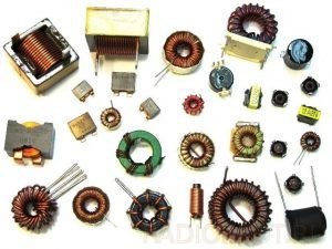
While the capacitor stores energy in an electrical field, the inductor stores energy in a magnetic field. Inductance is the inductor’s capacity to resist variation of electric current and is measured in henries (H). The inductor is nothing more than a rolled wire in spirals which can have a nucleus inside to increase the magnetic field and the inductance. Here are various types of inductors. Sometimes inductors are called solenoids.

The formula to calculate inductance:
- is the magnetic permeability;
- is the number of spires or turns in the inductor;
- is the section area;
- is the length.
The inductor’s association in series and in parallel is equal to the resistors and the total inductance is calculated in the same way.
Impedance and Reactance
In alternated current, the value of resistance in the passive components (resistor, capacitor and inductor) is called impedance, which is formed by reactances. In the resistor the impedance is equal the resistance value in the CC. In capacitors and inductors, the reactance is an imaginary number and are called respectively capacitive reactance and inductive reactance.
Capacitive reactance.
- is the capacitance and is the circuit’s frequency in radians/s.
Inductive reactance.
This graphic shows the impedance as Z, reactances as and in the imaginary axis and the resistance in the real numbers axis.
A number of electrical laws apply to all electrical networks. These include:
- Kirchhoff's current law: The sum of all currents entering a node is equal to the sum of all currents leaving the node.
- Kirchhoff's voltage law: The directed sum of the electrical potential differences around a loop must be zero.
- Ohm's law: The voltage across a resistor is equal to the product of the resistance and the current flowing through it.
- Norton's theorem: Any network of voltage or current sources and resistors is electrically equivalent to an ideal current source in parallel with a single resistor.
- Thévenin's theorem: Any network of voltage or current sources and resistors is electrically equivalent to a single voltage source in series with a single resistor.
- Superposition theorem: In a linear network with several independent sources, the response in a particular branch when all the sources are acting simultaneously is equal to the linear sum of individual responses calculated by taking one independent source at a time.
Other more complex laws may be needed if the network contains nonlinear or reactive components. Non-linear self-regenerative heterodyning systems can be approximated. Applying these laws results in a set of simultaneous equations that can be solved either algebraically or numerically.
