AC MACHINES-1 (66761) Theory
8. Comprehend the principle of auto-transformer.
8.1. Describe auto-transformer.
Auto Transformer
An Auto Transformer is a transformer with only one winding wound on a laminated core. An auto transformer is similar to a two winding transformer but differ in the way the primary and secondary winding are interrelated. A part of the winding is common to both primary and secondary sides.
On load condition, a part of the load current is obtained directly from the supply and the remaining part is obtained by transformer action. An Auto transformer works as a voltage regulator.
Explanation of Auto Transformer with Circuit Diagram
In an ordinary transformer, the primary and the secondary windings are electrically insulated from each other but connected magnetically as shown in the figure below. While in auto transformer the primary and the secondary windings are connected magnetically as well as electrically. In fact, a part of the single continuous winding is common to both primary and secondary.
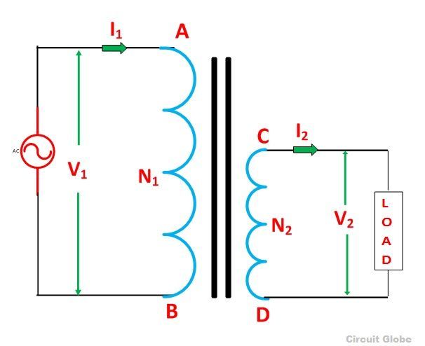
Figure A: Ordinary Two Winding Transformer
There are two types of auto transformer based on the construction. In one type of transformer, there is continuous winding with the taps brought out at convenient points determined by the desired secondary voltage. However, in another type of auto transformer, there are two or more distinct coils which are electrically connected to form a continuous winding. The construction of Auto transformer is shown in the figure below.

Figure B: Auto – Transformer
The primary winding AB from which a tapping at C is taken, such that CB acts as a secondary winding. The supply voltage is applied across AB, and the load is connected across CB. The tapping may be fixed or variable. When an AC voltage V1 is applied across AB, an alternating flux is set up in the core, as a result, an emf E1 is induced in the winding AB. A part of this induced emf is taken in the secondary circuit.
Let,
- V1 – primary applied voltage
- V2 – secondary voltage across the load
- I1 – primary current
- I2 – load current
- N1 – number of turns between A and B
- N2 – number of turns between C and B
Neglecting no-load current, leakage reactance and losses,
V1 = E1 and V2 = E2
Therefore, the transformation ratio: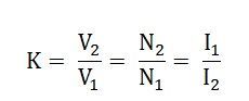
As the secondary ampere-turns are opposite to primary ampere-turns, so the current I2 is in phase opposition to I1. The secondary voltage is less than the primary. Therefore current I2 is more than the current I1. Therefore, the resulting current flowing through section BC is (I2 – I1).
The ampere-turns due to section BC = current x turns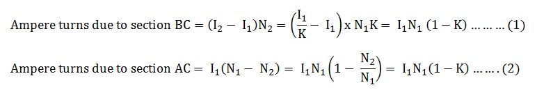 Equation (1) and (2) shows that the ampere-turns due to section BC and AC balance each other which is characteristic of the transformer action.
Saving of Copper in Auto Transformer as Compared to Ordinary Two Winding Transformer
The weight of the copper is proportional to the length and area of a cross-section of the conductor.
The length of the conductor is proportional to the number of turns, and the cross-section is proportional to the product of current and number of turns.
Now, from the above figure (B) shown of the auto transformer, the weight of copper required in an auto transformer is
Wa = weight of copper in section AC + weight of copper in section CB
Therefore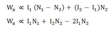
If the same duty is performed with an ordinary two winding transformer shown above in the figure (A), the total weight of the copper required in the ordinary transformer,
W0 = weight of copper on its primary winding + weight of copper on its secondary winding
Therefore,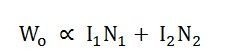
Now, the ratio of the weight of the copper in an auto transformer to the weight of copper in an ordinary transformer is given as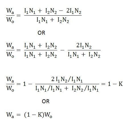
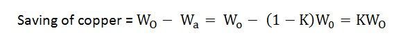
Saving of copper affected by using an auto transformer = weight of copper required in an ordinary transformer – weight of copper required in an auto transformer
 Therefore,
Saving of copper = K x weight of copper required for two windings of the transformer
Hence, saving in copper increases as the transformation ratio approaches unity. Hence the auto transformer is used when the value of K is nearly equal to unity.