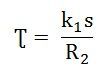
Starting torque is the torque produced by induction motor when it starts. We know that at the start the rotor speed, N is zero.

So, the equation of starting torque is easily obtained by simply putting the value of s = 1 in the equation of torque of the three phase induction motor,
The starting torque is also known as standstill torque.
Maximum Torque Condition for Three-Phase Induction Motor
In the equation of torque,
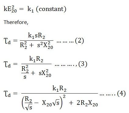
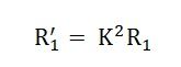
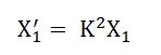
The rotor resistance, rotor inductive reactance and synchronous speed of induction motor remain constant. The supply voltage to the three phase induction motor is usually rated and remains constant, so the stator emf also remains the constant. We define the transformation ratio as the ratio of rotor emf to that of stator emf. So if stator emf remains constant, then rotor emf also remains constant.
If we want to find the maximum value of some quantity, then we have to differentiate that quantity concerning some variable parameter and then put it equal to zero. In this case, we have to find the condition for maximum torque, so we have to differentiate torque concerning some variable quantity which is the slip, s in this case as all other parameters in the equation of torque remains constant.
So, for torque to be maximum
Now differentiate the above equation by using division rule of differentiation. On differentiating and after putting the terms equal to zero we get,

Neglecting the negative value of slip we get
So, when slip s = R2 / X2, the torque will be maximum and this slip is called maximum slip Sm and it is defined as the ratio of rotor resistance to that of rotor reactance.
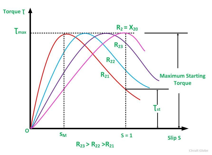
NOTE: At starting S = 1, so the maximum starting torque occur when rotor resistance is equal to rotor reactance.
Equation of Maximum Torque
The equation of torque is
The torque will be maximum when slip s = R2 / X2
Substituting the value of this slip in above equation we get the maximum value of torque as,

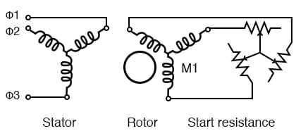
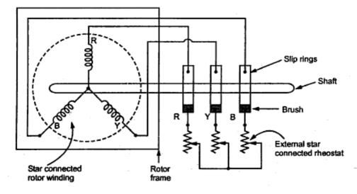
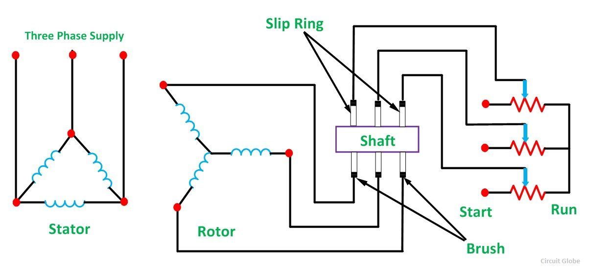
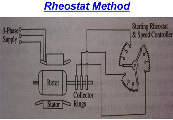
In order to increase the starting torque, extra resistance should be added to the rotor circuit at start and cut out gradually as motor speeds up.
Conclusion
From the above equation it is concluded that
- The maximum torque is directly proportional to square of rotor induced emf at the standstill.
- The maximum torque is inversely proportional to rotor reactance.
- The maximum torque is independent of rotor resistance.
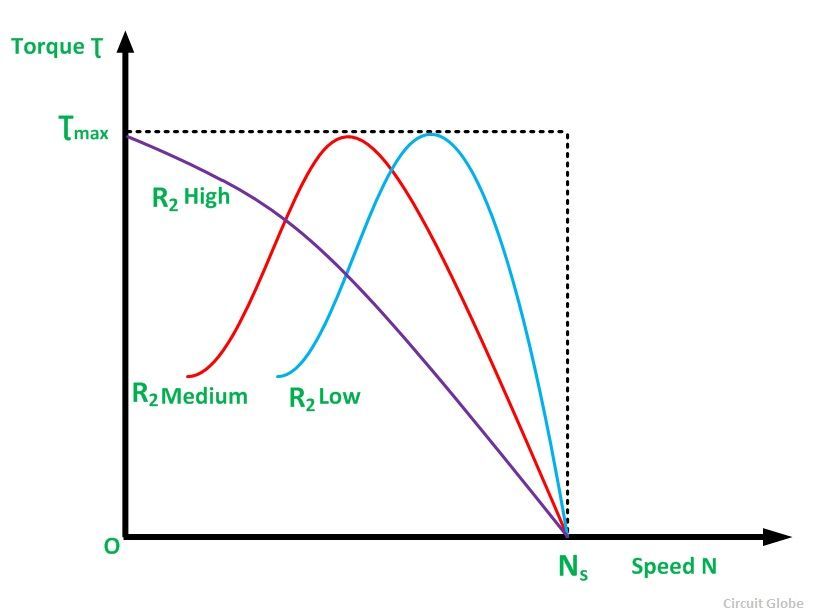
- The slip at which maximum torque occur depends upon rotor resistance, R2. So, by varying the rotor resistance, maximum torque can be obtained at any required slip.


What is the condition for maximum starting torque?
Maximum starting torque is obtained when the slip is equal to the ratio between the rotor resistance (r2) and the rotor inductive reactance (x2). This slip is also known as slip at maximum torque, labelled as Smt.
Maximum Torque Condition of an Induction Motor
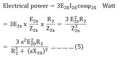
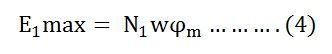
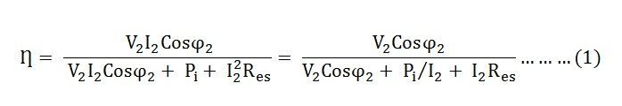
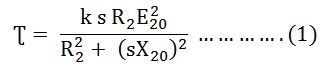
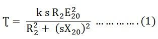
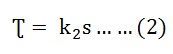
In the article named Torque Equation of an Induction motor, we have seen the developed torque and its equation. Here, the Maximum Torque Condition of an induction motor is discussed. The torque produced in the induction motor mainly depends on the following three factors. They are the strength of the rotor current; the flux interacts between the rotor of the motor and the power factor of the rotor.The value of torque when the motor is running is given by the equation shown below.
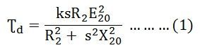
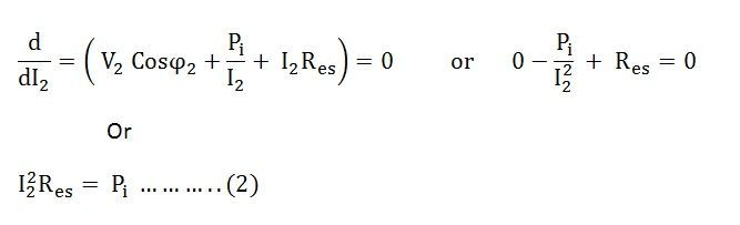
The developed torque will be maximum when the right-hand side of the equation (4) will be maximum. This condition is possible when the value of the denominator shown below is equal to zero.
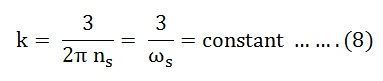
Let,
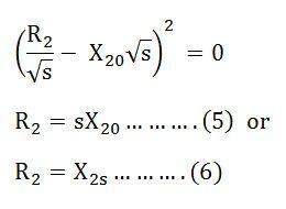
Hence. The developed torque is maximum when the rotor resistance per phase is equal to the rotor reactance per phase under running conditions. By putting the value of sX20 = R2 in the equation (1) we get the equation for maximum torque.
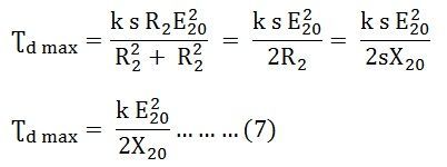
The above equation shows that the maximum torque is independent of the rotor resistance.
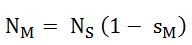
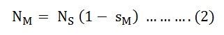
If sM is the value of slip corresponding to the torque which is maximum then from the equation (5)
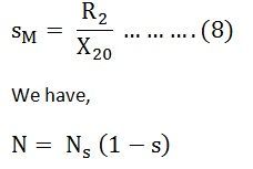
Therefore, The speed of the rotor at maximum torque is given by the equation shown below.
The following conclusion about the maximum torque can be drawn from the equation (7) are given below.
- It is independent of the rotor circuit resistance.
- Torque at the maximum condition varies inversely as the standstill reactance of the rotor. Hence, for maximum torque, X20 and therefore, the inductance of the rotor should be kept as small as possible.
- By varying the resistance in the rotor circuit, maximum torque can be obtained at any desired slip or the speed. It depends upon the rotor resistance at the slip (sM = R2/X20).
To develop maximum torque at the standstill condition, the rotor resistance must be high and should be equal to X20. But to develop a torque which is maximum at the running condition the rotor resistance must be low.
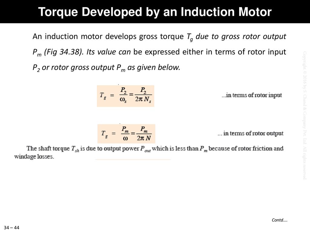
Torque Equation of an Induction Motor
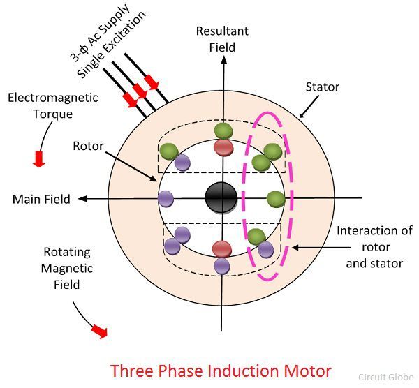
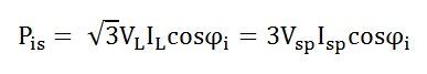
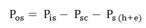
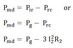
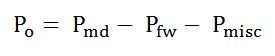
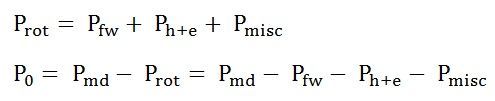
The developed Torque or Induced Torque Equation in a machine is defined as the Torque generated by the electric to mechanical power conversion. The torque is also known as Electromagnetic Torque. This developed torque in the motor differs from the actual torque available at the terminals of the motor, which is almost equal to the friction and windage torques on the machine.
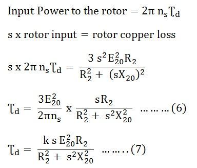
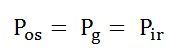
The developed torque equation is given as
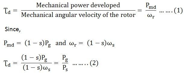
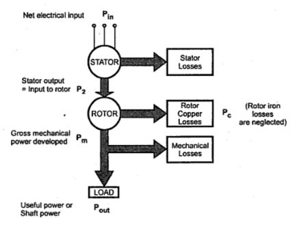
The above equation expresses the developed torque directly in terms of the air gap power Pg and the synchronous speed ωs. Since ωs is constant and independent of the load conditions. If the value of the Pg is known then, the developed torque can be found directly. The air gap power Pg is also called as the Torque in Synchronous Watts.
Synchronous Watt is the torque that develops the power of 1 Watt when the machine is running at synchronous speed.
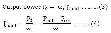
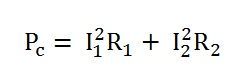
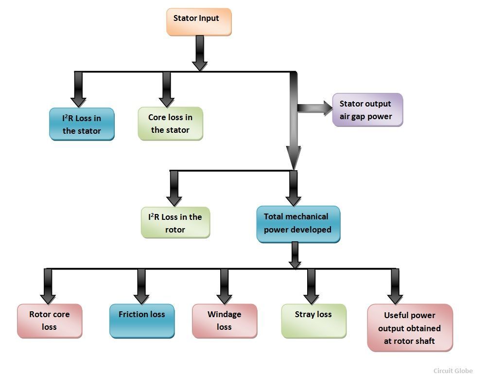
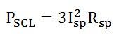
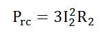
These electrical powers are dissipated as I2R losses or copper loss in the rotor circuit.
Input power to the rotor is given as
Where,
Starting Torque Of Induction Motor
At the start condition the value of s = 1. Therefore, the starting is obtained by putting the value of s = 1 in the equation (6), we get
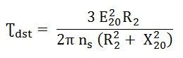
The starting torque is also known as Standstill Torque.
Torque Equation at Synchronous Speed
At synchronous speed, s = 0 and hence developed torque Ʈd = 0. At synchronous speed, developed torque is zero.
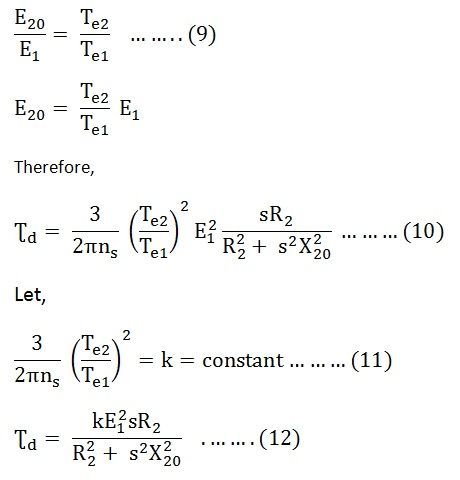
Since E1 is nearly equal to V1 the equation (12) becomes
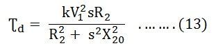
The Starting torque is obtained by putting s = 1 in equation (13)
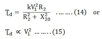
Hence, it is clear from the above equation that the starting torque is proportional to the square of the stator applied voltage.
Also See: Maximum Torque Condition of an Induction Motor
Maximum Torque Condition of an Induction Motor
In the article named Torque Equation of an Induction motor, we have seen the developed torque and its equation. Here, the Maximum Torque Condition of an induction motor is discussed. The torque produced in the induction motor mainly depends on the following three factors. They are the strength of the rotor current; the flux interacts between the rotor of the motor and the power factor of the rotor.The value of torque when the motor is running is given by the equation shown below.
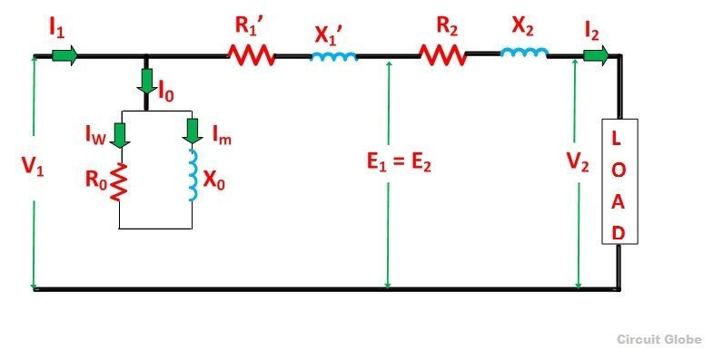
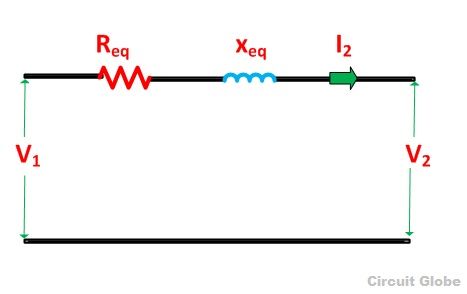
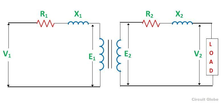
The total impedance of the RC network always lies between 0º and 90º. The impedance is the opposition offered by the electronic circuit element to the flow of current. If the impedance of the stator winding is assumed to be negligible. Thus, for the given supply voltage V1, E20 remains constant.
The developed torque will be maximum when the right-hand side of the equation (4) will be maximum. This condition is possible when the value of the denominator shown below is equal to zero.
Let,
Hence. The developed torque is maximum when the rotor resistance per phase is equal to the rotor reactance per phase under running conditions. By putting the value of sX20 = R2 in the equation (1) we get the equation for maximum torque.
The above equation shows that the maximum torque is independent of the rotor resistance.
If sM is the value of slip corresponding to the torque which is maximum then from the equation (5)
Therefore, The speed of the rotor at maximum torque is given by the equation shown below.
The following conclusion about the maximum torque can be drawn from the equation (7) are given below.
- It is independent of the rotor circuit resistance.
- Torque at the maximum condition varies inversely as the standstill reactance of the rotor. Hence, for maximum torque, X20 and therefore, the inductance of the rotor should be kept as small as possible.
- By varying the resistance in the rotor circuit, maximum torque can be obtained at any desired slip or the speed. It depends upon the rotor resistance at the slip (sM = R2/X20).
To develop maximum torque at the standstill condition, the rotor resistance must be high and should be equal to X20. But to develop a torque which is maximum at the running condition the rotor resistance must be low.


 3.
3.


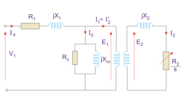

_2.png "Induction Motor Equivalent Circuit (1)")
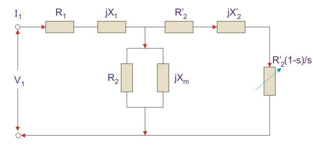
_2.png "Image(39)")
_2.png "Image(40)")


