AC MACHINES-1 (66761) Theory
10. Realize the principle and construction of 3-phase induction motor.
10.6. Narrate the construction of squirrel cage rotor, double squirrel cage rotor and phase wound rotor of induction motor.
The Rotor: Squirrel Cage Rotor:
A squirrel cage rotor has very low resistance bars cast into the rotor steel which acts as the secondary windings. A slip ring (wound rotor) motor has insulated wire rotor windings which feed out through slip rings to a bank of large variable resistors where the resistance of the rotor circuit can be varied.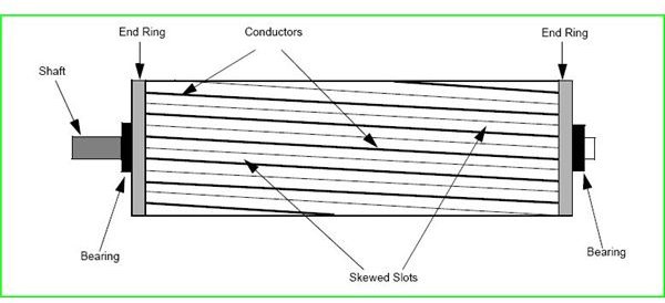
Construction of double squirrel cage rotor
 |
| cross section of double squirrel cage rotor |
Working of double squirrel cage motor
When the double cage motor is running at normal speed, frequency of the rotor emf is so low that the reactance of both cages is negligible. The two cages being connected in parallel, the combined resistance is lower.
The torque speed characteristics of double squirrel cage motor for both the cages are shown in the figure below.
CONSTRUCTION DETAILS
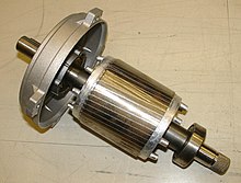
A three-phase, wound-rotor induction motor consists of a stator core with a three-phase winding, a wound rotor with slip rings, brushes and brush holders, and two end shields to house the bearings that support the rotor shaft.
ills 1, 2, 3, and 4 show the basic parts of a three-phase, wound-rotor induction motor.

ill. 1 Parts of a wound-rotor motor

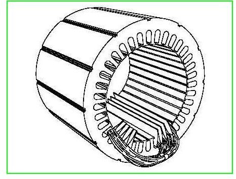
ill. 2 Wound stator for a polyphase induction motor

ill. 3 Wound rotor for a polyphase induction motor

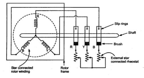
A wound rotor induction motor has a stator like a squirrel cage induction motor, but a rotor with insulated windings brought out via slip rings and brushes.
However, no power is applied to the slip rings. Their sole purpose is to allow resistance to be placed in series with the rotor windings while starting (figure below). This resistance is shorted out once the motor is started to make the rotor look electrically like the squirrel cage counterpart.
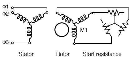
Wound rotor induction motor
- In Wound Rotor Induction Motor, the rotor has a 3 phase winding similar to stator winding.
- Rotor is also cylindrical in shape and has slots to carry winding
- The winding is placed evenly on slots of the rotor.
- are connected to 3 slip rings.
- These slip rings are mounted on the shaft.
- Each phase is connected to one of the three slip rings. These slip rings are associated with brushes.
- The three slip rings rotate with rotor, while brushes remain stationary.