AC MACHINES-1 (66761) Theory
11. Recognize the concept of development of rotating magnetic field and torque in rotor.
11.1. Explain the development of rotating magnetic field for three phase induction motor.
Production of Rotating Magnetic Field
The production of Rotating magnetic field in 3 phase supply is very interesting.
When a 3-phase winding is energized from a 3-phase supply, a rotating magnetic field is produced. This field is such that its poles do no remain in a fixed position on the stator but go on shifting their positions around the stator. For this reason, it is called a rotating field.
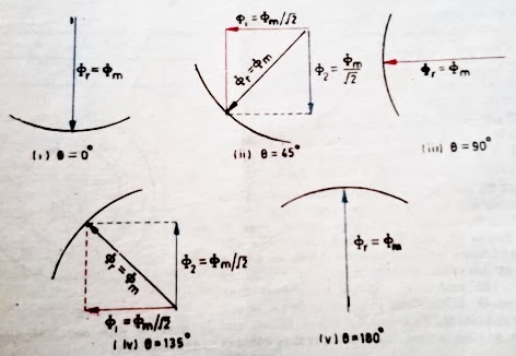
It can be shown that the magnitude of this rotating field is constant and is equal to 1.5 fm where fm is the maximum flux due to any phase.
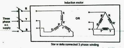
A three-phase induction motor consists of three phases winding as its stationary part called stator. The three-phase stator winding is connected in star or delta.
The three-phase windings are displaced from each other by 120°. The windings are supplied by a balanced three phase ac supply.
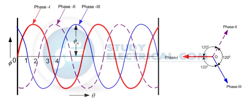
The three-phase currents flow simultaneously through the windings and are displaced from each other by 120° electrical. Each alternating phase current produces its own flux which is sinusoidal.
So all three fluxes are sinusoidal and are separated from each other by 120°.
If the phase sequence of the windings is R-Y-B, then mathematical equations for the instantaneous values of the three fluxes ΦR , ΦY ,ΦB can be written as,
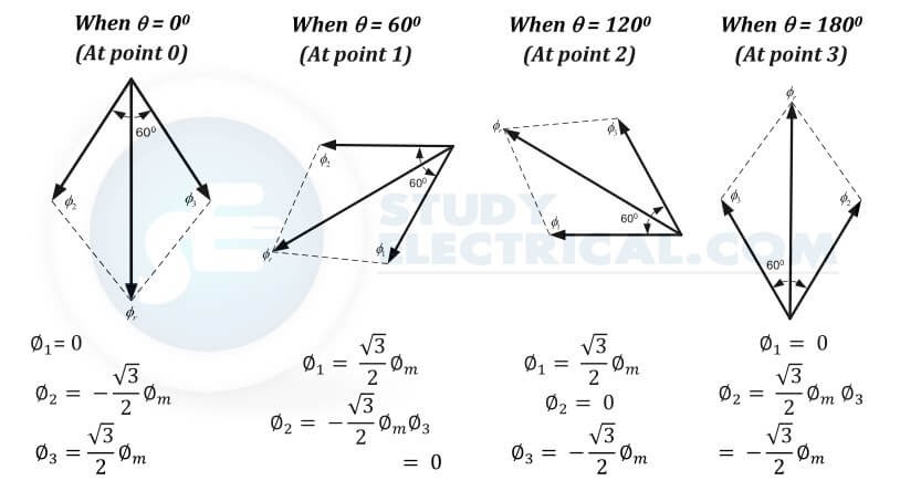
Case 1 : Wt = 0
ΦR = Φmsin(0) = 0
ΦY = Φmsin(0 – 120) = -0.866 Φm
ΦB = Φmsin(0 – 240) = +0.866 Φm
Case 2 : ωt = 60
ΦR = Φmsin(60) = +0.866 Φm
ΦY = Φmsin(- 60) = -0.866 Φm
ΦB = Φmsin(- 180) = 0
Case 3 : ωt = 120
ΦR = Φmsin(120) = +0.866 Φm
ΦY = Φmsin(0) = 0
ΦB = Φmsin(- 120) = -0.866 Φm
Case 4 : ωt = 180
ΦR = Φmsin(180) = 0
ΦY = Φmsin(60) = +.866 Φm
ΦB = Φmsin(- 60) = -0.866 Φm
In general, for P poles, the rotating field makes one revolution in P/2 cycles of current.


Since revolutions per second is equal to the revolutions per minute (N s ) divided by 60 and the number of cycles per second is the frequency f,


The speed of the rotating magnetic field is the same as the speed of the alternator that is supplying power to the motor if the two have the same number of poles. Hence the magnetic flux is said to rotate at synchronous speed.