


Here, the value of φR is
The value of φY is
The value of φB is
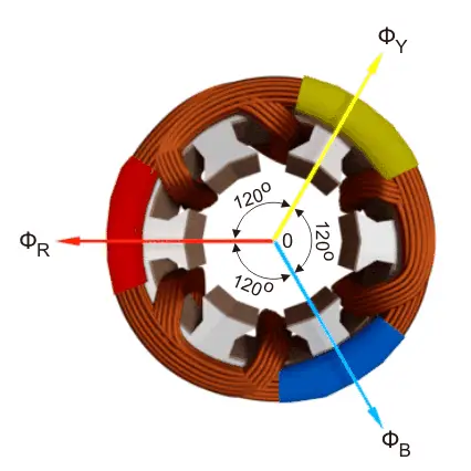
The resultant of these fluxes at that instant (φr) is 1.5φm which is shown in the figure below. here it is clear thet the resultant flux vector is rotated 30o further clockwise without changing its value.

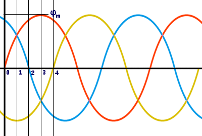
Now, on the graphical representation of flux waves, we will consider the point 2, where ωt = π / 3 or 60o.
Here, the value of φR is
The value of φY is
The value of φB is
The resultant of these fluxes at that instant (φr) is 1.5φm which is shown in the figure below. here it is clear thet the resultant flux vector is rotated 30° further clockwise without changing its value.

Now, on the graphical representation of flux waves, we will consider the point 3, where ωt = π / 2 or 90o.
Here, the value of φR is
The value of φY is
The value of φB is
The resultant of these fluxes at that instant (φr) is 1.5φm which is shown in the figure below. here it is clear thet the resultant flux vector is rotated 30o further clockwise without changing its value.

In this way we can prove that the due to balanced supply applied to the three pfase stator winding a rotating or revolving magnetic fiels is established in thew space.