AC MACHINES-1 (66761) Theory
12. Perceive the concept of Power stages of induction motor.
Power Stages in an Induction Motor
Different stages of power development in an induction motor
• Stator iron loss (consisting of eddy and hysteresis losses) depends on
the supply frequency and the flux density in the iron core. It is
practically constant.
• The iron loss of the rotor is, however,
negligible because frequency of rotor currents under normal running
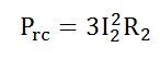
conditions is always small. Total rotor Cu loss = 3 I2
2R2.
An induction motor develops gross torque Tg due to gross rotor
output Pm.
• Its value can be expressed either in terms of rotor input P2 or rotor
gross output Pm as given below.
Power Flow Diagram of Induction Motor explains the input given to the motor, the losses occurring and the output of the motor. The input power given to an Induction motor is in the form of three-phase voltage and currents. The Power Flow Diagram of an Induction Motor is shown below.Power Flow Diagram and Losses of Induction Motor
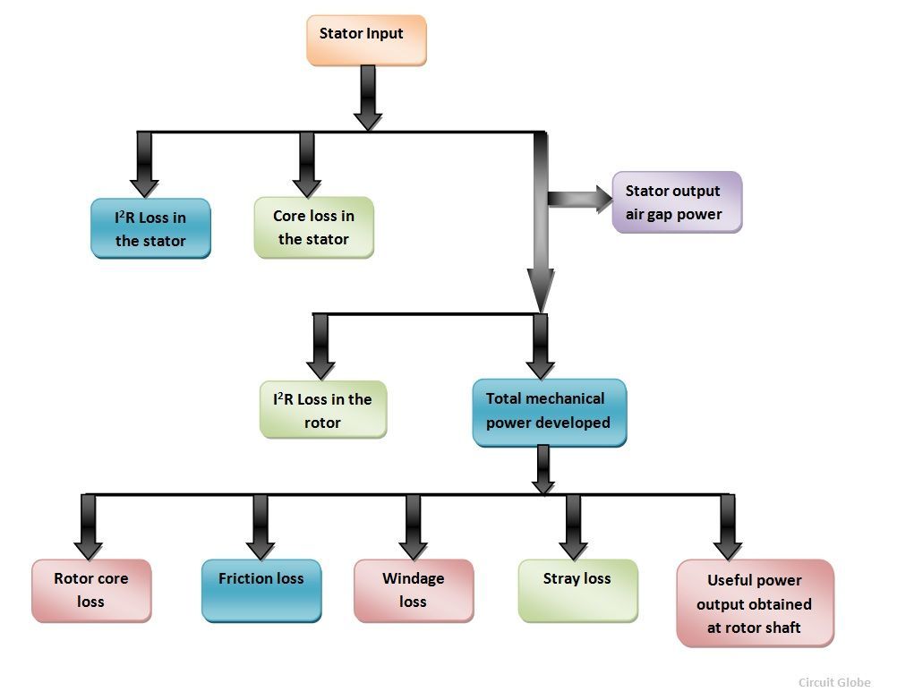
The power flow is given by the equation shown below.
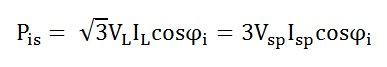
Where cosϕi is the input power factor
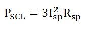
The losses in the stator are
I2R losses in the stator winding resistances. It is also known as Stator copper losses.
Hysteresis and Eddy current losses in the stator core. These are known as Stator core losses.
![]()
The output power of the stator is given as
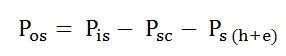
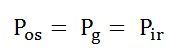
This output power of the stator is transferred to the rotor of the machine across the air gap between the stator and the rotor. It is called the air gap Pg of the machine.
Thus,
The Power output of the stator = air gap power = input power to the rotor
The losses in the rotor are as follows.
I2R losses in the rotor resistance. They are also called Rotor copper losses and represented as
Hysteresis and eddy current losses in the rotor core. They are known as Rotor core losses.
![]()
Friction and Windage losses Pfw
Stray load losses Pmisc, consisting of all losses not covered above, such as losses due to harmonic fields.
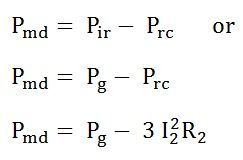
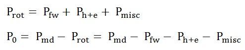
If the rotor copper losses are subtracted from rotor input power Pg, the remaining power is converted from electrical to mechanical form. This is called Developed Mechanical Power Pmd.
Developed Mechanical power = Rotor input – Rotor copper loss
The output of the motor is given by the equation shown below.
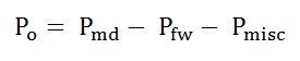
Po is called the shaft power or the useful power.
Rotational losses
At starting and during acceleration, the rotor core losses are high. With the increase in the speed of the induction motor these losses decreases. The friction and windage losses are zero at the start. As the speed increases the losses, also start increasing. The sum of the friction, windage and core losses are almost constant with the change in speed. These all losses are added together and are known as Rotational Losses.
It is given by the equation shown below.
The Rotational losses are not represented by any element of the equivalent circuit as they are purely mechanical quantity.