AC MACHINES-1 (66761) Theory
Completion requirements
15. Understand the principle of speed control of induction motor.
15.3. Describe rheostat control method, concatenation method & injecting emf in rotor circuit method.
Speed control from rotor side:
1. Rotor rheostat control
This method is similar to that of armature rheostat control of DC shunt motor. But this method is only applicable to slip ring motors, as addition of external resistance in the rotor of squirrel cage motors is not possible.2. Cascade operation
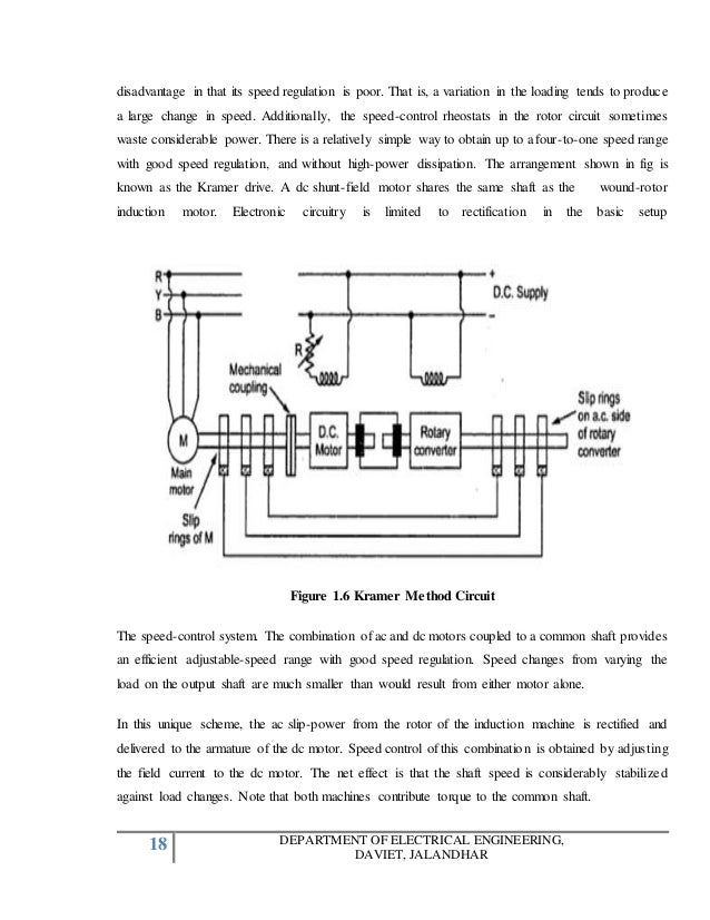
In this method of speed control, two motors are used. Both are mounted on a same shaft so that both run at same speed. One motor is fed from a 3phase supply and the other motor is fed from the induced emf in first motor via slip-rings. The arrangement is as shown in following figure.
Let, Ns1 = frequency of motor A
Ns2 = frequency of motor B
P1 = number of poles stator of motor A
P2 = number of stator poles of motor B
N = speed of the set and same for both motors
f = frequency of the supply
Now, slip of motor A, S1 = (Ns1 - N) / Ns1.
frequency of the rotor induced emf in motor A, f1 = S1f
Now, auxiliary motor B is supplied with the rotor induce emf
therefore, Ns2 = (120f1) / P2 = (120S1f) / P2.
now putting the value of S1 = (Ns1 - N) / Ns1

i.e. N = Ns2.
from the above equations, it can be obtained that

1. when only motor A works, corresponding speed = .Ns1 = 120f / P1
2. when only motor B works, corresponding speed = Ns2 = 120f / P2
3. if commulative cascading is done, speed of the set = N = 120f / (P1 + P2)
4. if differential cascading is done, speed of the set = N = 120f (P1 - P2)
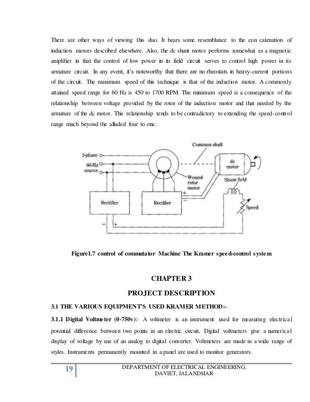
3. By injecting EMF in rotor circuit
In this method, speed of an induction motor is controlled by injecting a voltage in rotor circuit. It is necessary that voltage (emf) being injected must have same frequency as of the slip frequency. However, there is no restriction to the phase of injected emf. If we inject emf which is in opposite phase with the rotor induced emf, rotor resistance will be increased. If we inject emf which is in phase with the rotor induced emf, rotor resistance will decrease. Thus, by changing the phase of injected emf, speed can be controlled. The main advantage of this method is a wide rage of speed control (above normal as well as below normal) can be achieved. The emf can be injected by various methods such as Kramer system, Scherbius system etc.