DATA COMMUNICATION SYSTEM
5. Understand multiplexing techniques (Chapter 5)
5.1
Define Multiplexing and De-multiplexing process of communication system.
5.2 State the necessity of multiplexing.
5.3 Mention the categories of multiplexing.
5.4 Define Frequency division multiplexing.
5.5 Describe Frequency division multiplexing and de-multiplexing technique with block diagram
5.6 Describe the Wave division multiplexing and De-multiplexing technique with block diagram
5.7 Define Time division multiplexing and of Code division multiplexing system
5.8 State difference between baseband and broadband transmission.
5.1 Define Multiplexing and De-multiplexing process of communication system.
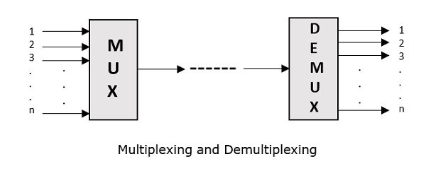
Multiplexing is the process of combining multiple signals into one signal, over a shared medium. If the analog signals are multiplexed, then it is called as analog multiplexing. Similarly, if the digital signals are multiplexed, then it is called as digital multiplexing.
Multiplexing was first developed in telephony. A number of signals were combined to send through a single cable. The process of multiplexing divides a communication channel into several number of logical channels, allotting each one for a different message signal or a data stream to be transferred. The device that does multiplexing can be called as Multiplexer or MUX.
The reverse process, i.e., extracting the number of channels from one, which is done at the receiver is called as de-multiplexing. The device that does de-multiplexing can be called as de-multiplexer or DEMUX.
The following figures illustrates the concept of MUX and DEMUX. Their primary use is in the field of communications.

5.2 State the necessity of multiplexing.
5.3 Mention the categories of multiplexing.
Types of Multiplexers
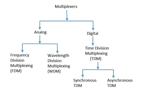
There are mainly two types of multiplexers, namely analog and digital. They are further divided into Frequency Division Multiplexing (FDM), Wavelength Division Multiplexing (WDM), and Time Division Multiplexing (TDM). There are another multiplexer which is CODE DIVISION Multiplexing .The following figure gives a detailed idea about this classification.

There are many types of multiplexing techniques. Out of which, we have the main types with general classification, mentioned in the above figure. Let us take a look at them individually.
Analog Multiplexing
The signals used in analog multiplexing techniques are analog in nature. The analog signals are multiplexed according to their frequency (FDM) or wavelength (WDM).
Frequency Division Multiplexing
In analog multiplexing, the most used technique is Frequency Division Multiplexing (FDM). This technique uses various frequencies to combine streams of data, for sending them on a communication medium, as a single signal.
Example − A traditional television transmitter, which sends a number of channels through a single cable uses FDM.
Wavelength Division Multiplexing
Wavelength Division multiplexing (WDM) is an analog technique, in which many data streams of different wavelengths are transmitted in the light spectrum. If the wavelength increases, the frequency of the signal decreases. A prism, which can turn different wavelengths into a single line, can be used at the output of MUX and input of DEMUX.
Example − Optical fiber communications use WDM technique, to merge different wavelengths into a single light for communication.
Digital Multiplexing
The term digital represents the discrete bits of information. Hence, the available data is in the form of frames or packets, which are discrete.
Time Division Multiplexing
In Time Division Multiplexing (TDM), the time frame is divided into slots. This technique is used to transmit a signal over a single communication channel, by allotting one slot for each message.
Time Division Multiplexing (TDM) can be classified into Synchronous TDM and Asynchronous TDM.
Synchronous TDM
In Synchronous TDM, the input is connected to a frame. If there are ‘n’ number of connections, then the frame is divided into ‘n’ time slots. One slot is allocated for each input line.
In this technique, the sampling rate is common for all signals and hence the same clock input is given. The MUX allocates the same slot to each device at all times.
Asynchronous TDM
In Asynchronous TDM, the sampling rate is different for each of the signals and a common clock is not required. If the allotted device for a time slot transmits nothing and sits idle, then that slot can be allotted to another device, unlike synchronous
This type of TDM is used in Asynchronous transfer mode networks.
5.4 Define Frequency division multiplexing.
Frequency division multiplexing (FDM) is a technique of multiplexing which means combining more than one signal over a shared medium. In FDM, signals of different frequencies are combined for concurrent transmission.
Concept and Process
In FDM, the total bandwidth is divided to a set of frequency bands that do not overlap. Each of these bands is a carrier of a different signal that is generated and modulated by one of the sending devices. The frequency bands are separated from one another by strips of unused frequencies called the guard bands, to prevent overlapping of signals.
The modulated signals are combined together using a multiplexer (MUX) in the sending end. The combined signal is transmitted over the communication channel, thus allowing multiple independent data streams to be transmitted simultaneously. At the receiving end, the individual signals are extracted from the combined signal by the process of demultiplexing (DEMUX).
Example
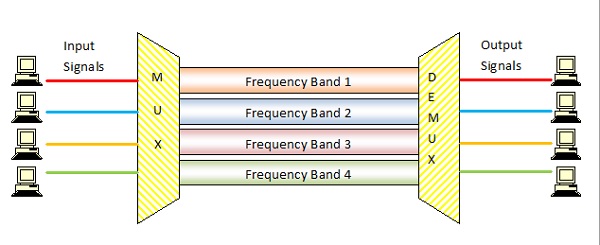
The following diagram conceptually represents multiplexing using FDM. It has 4 frequency bands, each of which can carry signal from 1 sender to 1 receiver. Each of the 4 senders is allocated a frequency band. The four frequency bands are multiplexed and sent via the communication channel. At the receiving end, a demultiplexer regenerates the original four signals as outputs.

Here, if the frequency bands are of 150 KHz bandwidth separated by 10KHz guard bands, then the capacity of the communication channel should be at least 630 KHz (channels : 150 × 4 + guard bands : 10 × 3).
Uses and Applications
It allows sharing of a single transmission medium like a copper cable or a fiber optic cable, among multiple independent signals generated by multiple users.
FDM has been popularly used to multiplex calls in telephone networks. It can also be used in cellular networks, wireless networks and for satellite communications.
5.5 Describe Frequency division multiplexing and de-multiplexing technique with block diagram
Frequency Division Multiplexing (FDM) System
The operation of frequency division multiplexing (FDM) is based on sharing the available bandwidth of a communication channel among the signals to be transmitted .
This means that many signals are transmitted simultaneously with each signal occupying a different frequency slot within a common bandwidth .
Each signal to be transmitted modulates a different carrier . The modulation can be AM,SSB, FM or PM .
The modulated signals are then added together to form a composite signal which is transmitted over a single channel .
The spectrum of composite FDM signal has been shown in fig.1 .
Fig.1 : Spectrum of FDM Signal
Generally, the FDM systems are used for multiplexing the analog signals .
FDM Transmitter
Fig.2 shows the block diagram of an FDM transmitter .
Fig. 2 : FDM Transmitter
The signals which are to be multiplexed will each modulate a separate carrier .The type of modulation can be AM, SSB, FM or PM .
The modulated signals are then added together to form a complex signal which is transmitted over a single channel .
Working Operation of the FDM Transmitter
Each signal modulates a separate carrier . The modulator outputs will contain the sidebands of the corresponding signals .
The modulator outputs are added together in a linear mixer or adder .
The linear mixer is different from the normal mixers. Here the sum and difference frequency components are not produced . But only the algebraic addition of the modulated outputs will take place .
Different signals are thus added together i the time domain but they have a separate identity in the frequency domain . This is as shown in fig.2 .
The composite signal at the output of mixer is transmitted over the single communication channel as shown in fig.2 . This signal can be used to modulate a radio transmitter if the FDM signal is to be transmitted through air .
FDM Receiver
The block diagram of an FDM receiver is shown in fig.3 .
Fig.3 : FDM Receiver
The composite signal is applied to a group of bandpass filters (BPF) .
Each BPF has a center frequency corresponding to one of the carriers. The BPFs have an adequate bandwidth to pass all the channel information without any distortion .
Each filter will pass only its channel and rejects all the other channels .
The channel demodulator then removes the carrier and recovers the original signal back .
Wavelength Division Multiplexing (WDM)
In fiber communications, the WDM (Wavelength Division Multiplexing) is one type of technology. This is the most useful concept in high-capacity communication systems. At the end of the transmitter section, the multiplexer is used to combine the signals as well as at the end of receiver section, de-multiplexer for dividing the signals separately. The main function of WDM at the multiplexer is for uniting various light sources into an only light source, and this light can be changed into numerous light sources at the de-multiplexer.

5.8 State difference between baseband and broadband transmission.
Key Differences Between Baseband and Broadband Transmission
- Baseband transmission utilizes digital signalling while broadband transmission uses analog signalling.
- Bus and tree topologies, both work well with the broadband transmission. On the other hand, for the baseband transmission bus topology is suitable.
- Baseband involves manchester and differential manchester encoding. In contrast, broadband does not make use of any digital encoding instead it uses PSK (Phase shift keying) encoding.
- The signals can be travelled in both the direction in baseband transmission whereas in broadband transmission the signals can travel in only one direction.
- In baseband transmission, the signals cover shorter distances because at higher frequencies the attenuation is most pronounced which make a signal to travel short distances without reducing its power. As against, in broadband signals, the signals can be travelled at longer distances.


