AC MACHINES-1 (66761) Theory
2. Perceive the emf equation, transformation ratio and Losses of transformer.
2.2. Derive the emf equation of transformer.
EMF Equation of a Transformer
When a sinusoidal voltage is applied to the primary winding of a transformer, alternating flux ϕm sets up in the iron core of the transformer. This sinusoidal flux links with both primary and secondary winding. The function of flux is a sine function.
The rate of change of flux with respect to time is derived mathematically.
The derivation of the EMF Equation of the transformer is shown below. Let
- ϕm be the maximum value of flux in Weber
- f be the supply frequency in Hz
- N1 is the number of turns in the primary winding
- N2 is the number of turns in the secondary winding
Φ is the flux per turn in Weber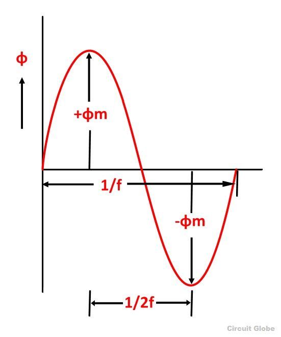 As shown in the above figure that the flux changes from + ϕm to – ϕm in half a cycle of 1/2f seconds.
By Faraday’s Law
Let E1 be the emf induced in the primary winding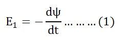
Where Ψ = N1ϕ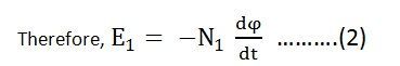
Since ϕ is due to AC supply ϕ = ϕm Sinwt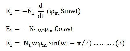
So the induced emf lags flux by 90 degrees.
Maximum valve of emf
But w = 2πf![]()
Root mean square RMS value is
Putting the value of E1max in equation (6) we get
Putting the value of π = 3.14 in the equation (7) we will get the value of E1 as
Similarly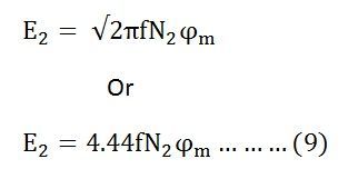
Now, equating the equation (8) and (9) we get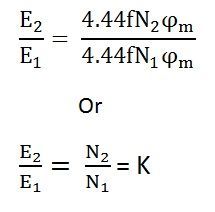
The above equation is called the turn ratio where K is known as the transformation ratio.
The equation (8) and (9) can also be written as shown below using the relation
(ϕm = Bm x Ai) where Ai is the iron area and Bm is the maximum value of flux density.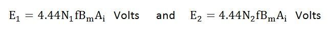
For a sinusoidal wave
Here 1.11 is the form factor.