AC MACHINES-1 (66761) Theory
Completion requirements
5. Realize the open circuit test, short circuit test and voltage regulation of transformer
5.1. Describe open circuit test.
5.1These two transformer tests are performed to find the parameters of equivalent circuit of transformer and losses of the transformer. Open circuit test and short circuit test on transformer are very economical and convenient because they are performed without actually loading of the transformer.
Open circuit or No load test on Transformer
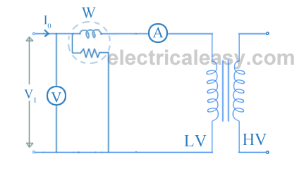
Open circuit test or no load test on a transformer is performed to determine 'no load loss (core loss)' and 'no load current I0'. The circuit diagram for open circuit test is shown in the figure below.
Usually high voltage (HV) winding is kept open and the low voltage (LV) winding is connected to its normal supply. A wattmeter (W), ammeter (A) and voltmeter (V) are connected to the LV winding as shown in the figure. Now, applied voltage is slowly increased from zero to normal rated value of the LV side with the help of a variac. When the applied voltage reaches to the rated value of the LV winding, readings from all the three instruments are taken.
The ammeter reading gives the no load current I0. As I0 itself is very small, the voltage drops due to this current can be neglected.
The input power is indicated by the wattmeter (W). And as the other side of transformer is open circuited, there is no output power. Hence, this input power only consists of core losses and copper losses. As described above, no-load current is so small that these copper losses can be neglected. Hence, now the input power is almost equal to the core losses. Thus, the wattmeter reading gives the core losses of the transformer.Sometimes, a high resistance voltmeter is connected across the HV winding. Though, a voltmeter is connected, HV winding can be treated as open circuit as the current through the voltmeter is negligibly small. This helps in to find voltage transformation ratio (K).
The two components of no load current can be given as,Iμ = I0sinΦ0 and Iw = I0cosΦ0.
cosΦ0 (no load power factor) = W / (V1I0). ... (W = wattmeter reading)
From this, shunt parameters of equivalent circuit parameters of equivalent circuit of transformer (X0 and R0) can be calculated as
X0 = V1/Iμ and R0 = V1/Iw.
(These values are referring to LV side of the transformer.)
Hence, it is seen that open circuit test gives
