AC MACHINES-1 (66761) Theory
Completion requirements
5. Realize the open circuit test, short circuit test and voltage regulation of transformer
5.2. Describe short circuit test.
Short circuit or Impedance test on Transformer
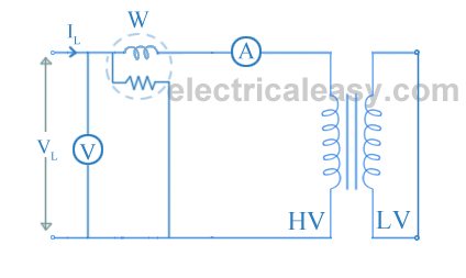
The connection diagram for short circuit test or impedance test on transformer is as shown in the figure below. The LV side of transformer is short circuited and wattmeter (W), voltmere (V) and ammeter (A) are connected on the HV side of the transformer. Voltage is applied to the HV side and increased from the zero until the ammeter reading equals the rated current. All the readings are taken at this rated current.The ammeter reading gives primary equivalent of full load current (Isc).
The voltage applied for full load current is very small as compared to rated voltage. Hence, core loss due to small applied voltage can be neglected. Thus, the wattmeter reading can be taken as copper loss in the transformer.
Therefore, W = Isc2Req....... (where Req is the equivalent resistance of transformer)
Zeq = Vsc/Isc.
Therefore, equivalent reactance of transformer can be calculated from the formula Zeq2 = Req2 + Xeq2.
These, values are referred to the HV side of the transformer.
Hence, it is seen that the short circuit test gives copper losses of transformer and approximate equivalent resistance and reactance of the transformer.

