AC MACHINES-1 (66761) Theory
5. Realize the open circuit test, short circuit test and voltage regulation of transformer
5.3. Draw the vector diagrams.
5.3
The phasor diagram of the transformer at no load or when an open circuit test is performed is shown below
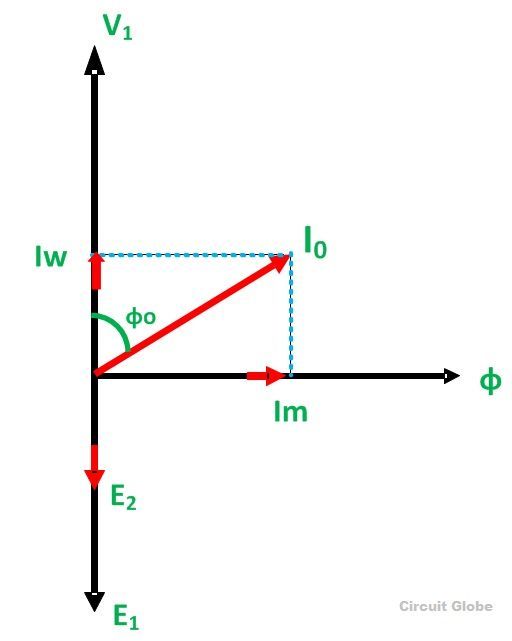
Phasor Diagram of Open Circuit Test
The iron losses measured by the open circuit test is used for calculating the efficiency of the transformer.
The phasor diagram of the short circuit test of the transformer is shown below
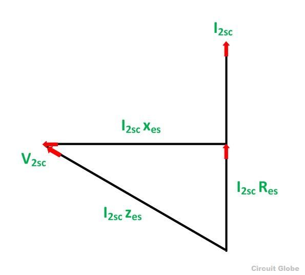
Phasor Diagram of Short Circuit Test
From the phasor diagram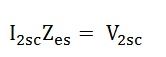
Equivalent impedance referred to the secondary side is given by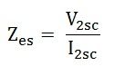
The equivalent reactance referred to the secondary side is given by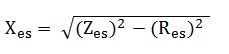
The voltage regulation of the transformer can be determined at any load and power factor after knowing the values of Zes and Res.
In the short circuit test the wattmeter record, the total losses, including core loss but the value of core loss are very small as compared to copper loss so the core loss can be neglected.