ALTERNATING CURRENT MACHINES – I(Practical:)
| Site: | jpilms.gnomio.com |
| Course: | Alternating Current Machines- 1 |
| Book: | ALTERNATING CURRENT MACHINES – I(Practical:) |
| Printed by: | Guest user |
| Date: | Thursday, 3 April 2025, 9:05 AM |
Description
1
Table of contents
- 1. Observe and determine the transformation ratio of a single phase transformer.
- 2. Perform the open circuit test of single phase transformer.
- 3. Perform the short circuit test of a single phase transformer.
- 4. Determine the voltage regulation of single phase transformer by direct loading.
- 5. Perform parallel operation of two single phase transformers.
- 6. Perform the polarity test of a single phase transformer.
- 7. Perform transformer banking.
- 8. Perform V-V and T-T connection of transformer banking.
- 9. Perform the operation of auto-transformer and determining its transformation ratio.
- 10. Perform the identification of the parts of a three phase induction motor.
- 11. Start a 3-phase induction motor by manual Star-delta starter.
- 12. Start a 3-phase induction motor by Star-delta starter using PLC.
1. Observe and determine the transformation ratio of a single phase transformer.
https://jpilms.gnomio.com/pluginfile.php/1051/mod_book/chapter/231/A%20C%20M%20-1%28Job.%20no-1%29%20Ratio.pptx
1. OBSERVE AND DETERMINE THE TRANSFORMATION RATIO OF A SINGLE PHASE TRANSFORMER.
1.1 Inspect a single phase transformer.
1.2 Sketch the circuit diagram.
1.3 List the tools, equipments & materials for the experiment.
1.4 Connect the equipment according to the circuit diagram.
1.5 Apply the voltage to the high side and connect the load to the low side.
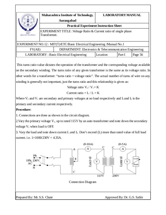
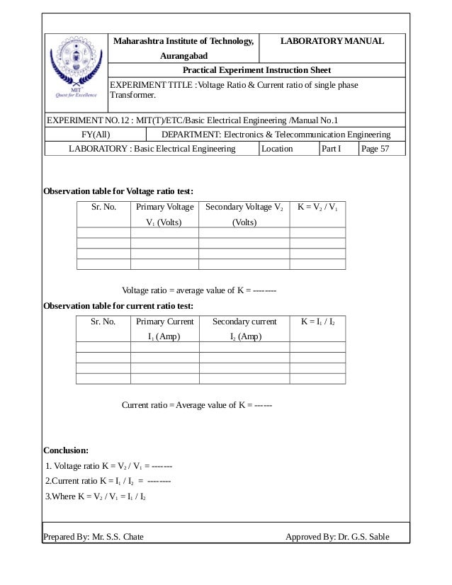
1.6 Tabulate the readings from the instruments and calculate the transformation ratio from
the formula:
2. Perform the open circuit test of single phase transformer.
2 Perform the open circuit test of single phase transformer.
2.1 Draw the circuit diagram.
2.2 List the tools, equipment & materials required.
2.3 Connect the equipment according to the diagram.
2.4 Connect the low side of its rated supply voltage keeping high side open.
2.5 Record the readings of the instruments.
2.6 Calculate Io, I, Iw, Ro and Xo.
2.7 Draw no load vector diagram using the data obtained.
Open circuit or No load test on Transformer
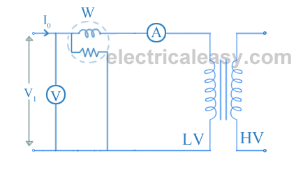
Open circuit test or no load test on a transformer is performed to determine 'no load loss (core loss)' and 'no load current I0'. The circuit diagram for open circuit test is shown in the figure below.Usually high voltage (HV) winding is kept open and the low voltage (LV) winding is connected to its normal supply. A wattmeter (W), ammeter (A) and voltmeter (V) are connected to the LV winding as shown in the figure. Now, applied voltage is slowly increased from zero to normal rated value of the LV side with the help of a variac. When the applied voltage reaches to the rated value of the LV winding, readings from all the three instruments are taken.
Iμ = I0sinΦ0 and Iw = I0cosΦ0.
cosΦ0 (no load power factor) = W / (V1I0). ... (W = wattmeter reading)
From this, shunt parameters of equivalent circuit parameters of equivalent circuit of transformer (X0 and R0) can be calculated as
X0 = V1/Iμ and R0 = V1/Iw.
(These values are referring to LV side of the transformer.)
Hence, it is seen that open circuit test gives core losses of transformer and shunt parameters of the equivalent circuit.
Open Circuit test procedure. A watt meter and an ammeter is connected in series with LV winding to measure the open circuit power and excitation current of the transformer. A Voltmeter is connected in parallel with the voltage source to read the test voltage applied to it. The HV winding is kept open.

3. Perform the short circuit test of a single phase transformer.
Perform the short circuit test of a single phase transformer.
3.1 Sketch the required circuit diagram.
3.2 List tools, equipment & materials required.
3.3 Connect the equipment according to the circuit diagram keeping high side to the
source.
3.4 Short circuit the low side by a low resistance wire.
3.5 Energize the circuit by applying reduced voltage and increase the voltage until it takes
full load of current.
3.6 Record the instrument readings.
3.7 Observe copper loss and calculate and find Re, Xe & Ze.
1. Short Circuit Test on Transformer
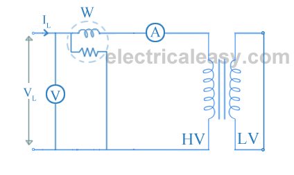
The connection diagram for the short circuit test on the transformer is shown in the figure below. A voltmeter, wattmeter, and an ammeter are connected in HV side of the transformer as shown. A low voltage of around 5-10% is applied to that HV side with the help of a variac (i.e. a variable ratio auto transformer). We short-circuit the LV side of the transformer. Now with the help of variac applied voltage is slowly increased until the wattmeter, and an ammeter gives reading equal to the rated current of the HV side.
After reaching the rated current of the HV side, we record all the three instrument readings (Voltmeter, Ammeter and Watt-meter readings). The ammeter reading gives the primary equivalent of full load current IL. As the voltage applied for full load current in a short circuit test on the transformer is quite small compared to the rated primary voltage of the transformer, the core losses in the transformer can be taken as negligible here.

Let’s say, voltmeter reading is Vsc. The watt-meter reading indicates the input power during the test. As we have short-circuited the transformer, there is no output; hence the input power here consists of copper losses in the transformer. Since the applied voltage Vsc is short circuit voltage in the transformer and hence it is quite small compared to the rated voltage, so, we can neglect the core loss due to the small applied voltage. Hence the wattmeter reading can be taken as equal to copper losses in the transformer. Let us consider wattmeter reading is Psc.

If, Ze is equivalent impedance of transformer.

Therefore, if equivalent reactance of transformer is Xe.

These values are referred to the HV side of the transformer as the test is conducted on the HV side of the transformer. These values could easily be converted to the LV side by dividing these values with the square of transformation ratio.
Hence the short-circuit test of a transformer is used to determine copper losses in the transformer at full load. It is also used to obtain the parameters to approximate the equivalent circuit of a
2.Short circuit or Impedance test on Transformer
The connection diagram for short circuit test or impedance test on transformer is as shown in the figure below. The LV side of transformer is short circuited and wattmeter (W), voltmere (V) and ammeter (A) are connected on the HV side of the transformer. Voltage is applied to the HV side and increased from the zero until the ammeter reading equals the rated current. All the readings are taken at this rated current.The ammeter reading gives primary equivalent of full load current (Isc).
The voltage applied for full load current is very small as compared to rated voltage. Hence, core loss due to small applied voltage can be neglected. Thus, the wattmeter reading can be taken as copper loss in the transformer.
Therefore, W = Isc2Req....... (where Req is the equivalent resistance of transformer)
Zeq = Vsc/Isc.
Therefore, equivalent reactance of transformer can be calculated from the formula Zeq2 = Req2 + Xeq2.
These, values are referred to the HV side of the transformer.
Hence, it is seen that the short circuit test gives copper losses of transformer and approximate equivalent resistance and reactance of the transformer.
4. Determine the voltage regulation of single phase transformer by direct loading.
Determine the voltage regulation of single phase transformer by direct loading.
4.1 Sketch the necessary circuit diagram.
4.2 List the tools, equipment & materials required.
4.3 Connect the meters according to the diagram.
4.4 Connect the source to the primary keeping the secondary open and record no load
voltage (Vo).
4.5 Connect full load on the secondary & record the load voltage.
4.6 Calculate the voltage regulation from the formula:
Voltage Regulation of a Transformer
Definition: The voltage regulation is defined as the change in the magnitude of receiving and sending voltage of the transformer. The voltage regulation determines the ability of the transformer to provide the constant voltage for variable loads.
When the transformer is loaded with continuous supply voltage, the terminal voltage of the transformer varies. The variation of voltage depends on the load and its power factor.
Mathematically, the voltage regulation is represented as
The equation for the voltage regulation of transformer, represented in percentage, is
where,
E2 – secondary terminal voltage at no load
V2 – secondary terminal voltage at full load
The voltage regulation by considering the primary terminal voltage of the transformer is expressed as,
Aim:
To determine Regulation and Efficiency of a single phase (1 Ф) Transformer by direct loading test. Apparatus: -
Single phase dimmer stat, Ammeter (AC), Voltmeter (AC) Single phase transformer, Wattmeter, Resistive Load Bank
Regulation is defined as the ratio of change in terminal voltage from no load to full load to the no load voltage.
Efficiency is defined as the ratio of output power to the input
power of the transformer. Efficiency of a transformer varies with power
factor at different loads.

LOAD TEST:
The load on a large power transformer in a sub-station will vary from a very small
value in the early hours of the morning to a very high value during the heavy peaks of
maximum industrial and commercial activity. The transformer secondary voltage will vary
somewhat with the load, and because motors, incandescent lamps, and heating devices are all
quite sensitive to voltage changes, transformer regulation is of considerable importance. The
secondary voltage also depends upon whether the power factor of the load is leading, lagging,
or unity. Therefore, it should be known how the transformer will behave (its voltage
regulation) when connected to a capacitive, an inductive, or a resistive load.
This test is performed to determine the efficiency and regulation of a transformer at different load conditions. Usually, this test is performed for low, power, rating of transformers. This test gives accurate results as compared to the above tests. In this test, measurements are taken on HV side and LV side at different load conditions.
PROCEDURE:
Make the connections as the circuit diagram in Figure 3.
Keep the switch on secondary side open so that load is zero to measure no load
voltage. Also keep knob of auto transformer at zero output voltage position.
Now increase the voltage through auto transformer until the voltage at secondary
winding at its rated value.
Adjust the switches on the Resistive Load module to successively increase the
loading factor.
For each resistance value, record the readings from Wattmeter, Voltmeter, &
Ammeter.
Switch off the AC-Supply.
5. Perform parallel operation of two single phase transformers.
6.1 Draw the circuit diagram.
6.2 Collect tools, equipment & materials required.
6.3 Connect the equipment according to the circuit diagram with proper polarity.
6.4 Energize the circuit and connect the load to the secondary.
6.5 Record the energy shared by each transformer.
6. Perform the polarity test of a single phase transformer.
Perform the polarity test of a single phase transformer.
5.1 Draw the required circuit diagram.
5.2 Collect tools, equipment & materials required.
5.3 Connect the equipment according to the diagram.
5.4 Connect the circuit to the source.
5.5 Record the voltmeter readings.
5.6 Determine whether it is additive or subtractive polarity.
We do polarity test on parallel transformers to ensure that we connect the same polarity windings and not the opposite ones. If we accidentally connect the opposite polarities of the windings, it will result in a short-circuit and eventually damage the machine.
We can categorise the polarity of the transformer to two types,
- Additive Polarity
- Subtractive Polarity

Additive Polarity
In additive polarity, the voltage (Vc) between the primary side (Va) and the secondary side (Vb) will be the sum of both high voltage and the low voltage, i.e. we will get Vc = Va + Vb
Subtractive Polarity
In subtractive polarity, the voltage (Vc) between the primary side (Va) and the secondary side (Vb) will be the difference of both high voltage and the low voltage, i.e. we will get Vc = Va – Vb
In subtractive polarity, if Vc = Va – Vb, it is a step-down transformer and if Vc = Vb – Va, it is a step-up transformer.
We use additive polarity for small-scale distribution transformers and subtractive polarity for large-scale transformers.
Procedure of Polarity Test of Transformer

- Connect the circuit as shown above with a voltmeter (Va) across primary winding and another voltmeter (Vb) across the secondary winding.
- If available, take down the ratings of the transformer and the turn ratio.
- We connect a voltmeter (Vc) between primary and secondary windings.
- We apply some voltage to the primary side.
- By checking the value in the voltmeter (Vc), we can find whether it is additive or subtractive polarity.
If additive polarity – Vc should be showing the sum of Va and Vb.
If subtractive polarity – Vc should be showing the difference between Va and Vb.
Caution: Be careful that the max. measuring the voltage of voltmeter Vc should be greater than the sum of Va (Primary winding) and Vb (Secondary winding) otherwise during the additive polarity, the sum of Va and Vb comes across it.
Note: If we require additive polarity, but we have subtractive polarity, we can simply change it by keeping any of the primary or secondary windings in the same fashion and reversing the winding connection of the other one. Similarly, if we require subtractive polarity but have additive polarity, we could do the same procedure as above
7. Perform transformer banking.
Perform transformer banking.
7.1 Collect the tools, equipment and materials required.
7.2 Draw the circuit diagram of Y-Y, Y-, - and -Y banking respectively.
7.3 Connect the equipment according to the diagram separately.
7.4 Record the meter readings for each case separately.
7.5 Calculate the voltage ratio in each case.
8. Perform V-V and T-T connection of transformer banking.
Perform V-V and T-T connection of transformer banking.
8.1 Collect the tools, equipment and materials required.
8.2 Draw the circuit diagram of V-V connection respectively.
8.3 Draw the circuit diagram of T-connection respectively.
8.4 Connect the equipment according to the diagram separately.
8.5 Record the meter readings for each case separately.
8.6 Calculate the voltage ratio in each case.
9. Perform the operation of auto-transformer and determining its transformation ratio.
Perform the operation of auto-transformer and determining its transformation ratio.
9.1 Sketch the circuit diagram.
9.2 Collect tools, equipment & materials required.
9.3 Connect the equipment according to the circuit diagram.
9.4 Energize the circuit and tabulate the meter readings.
9.5 Calculate transformation ratio, conducted power & transformed power.
Auto Transformer Starting
Objectives
To start the induction motor using 3-phase auto-transformer.
Overview
In this method, an auto-transformer is placed in series with the motor during staring. The transformer action reduces the voltage applied to the motor terminals. Because of the transformer action, the line current is less than the motor current. For a given starting current on the line side, the motor terminal voltage can be higher than for other reduced voltage start methods. Thus, this method gives the highest motor torque per line ampere.
The auto- transformer is used to reduce the phase voltage to the fraction x of normal value. The advantage of the method lies in the fact that the voltage is reduced by transformation, not by dropping the excess in impedance, so that the line current and power input are reduced in comparison with stator resistance starting.
Neglecting magnetizing current and losses in the auto-transformer, the current on the output side is Is in the fraction of the turns, and on the input side will consequently be xIs = x2Ix in all the turns of each phase. Thus for a starting torque of x2 of that obtainable by direct switching, only x2 of the short-circuit current is taken from the line. Alternatively, for the same line current, the starting torque with the auto-transformer is 1/x times as great as that obtainable with the stator impedance startor.
The system of connections shown provides voltage steps during starting, the auto-transformer being cut completely out of service after the start has been completed. Since it is only in use for short periods, the current density in the windings may be increased considerably above that normal for power transformers. At the same time, since the starting torque depends on the square of the current, the impedance of the transformer should be kept small. The auto-connection is here of particular advantage.
Steps for Connection:
1. Connect CH1 of the oscilloscope to L21.
2. Connect CH2 and CH3 with the motor shaft.
3. Choose the red colour cable button.
4. Connect L21 to the one of the terminal of the ammeter.
5. Connect U1 to the other terminal of the ammeter.
6. Choose the green colour cable button Connect L22 to V1.
7. Connect w1 to one of the terminal of the voltmeter.
8. Choose the blue colour cable button Connect L32 to W1.
9. Connect w2 to the other terminal of the voltmeter
10. Choose the black colour cable button.
11. Connect U2 and V2
12. Connect V2 and W2
13. Click the check button and if the connection is correct, click OK.
14. If the connection is wrong, follow the error message displayed and correct the connection.
15. Select 1 on the two way switch on the left hand side of the panel.
16. Switch ON the MCB and click the start button.
17. Switch ON the second MCB.
18. Select star or delta by clicking the three way switch in the star delta starter
19. Note the readings of ammeter and voltmeter.
20. Select CH1, CH2 and CH3 button on Oscilloscope for instantaneous current , speed and torque reading
10. Perform the identification of the parts of a three phase induction motor.
Perform the identification of the parts of a three phase induction motor.
10.1 Select a 3-phase induction motor.
10.2 Collect different tools required for the experiment.
10.3 List different parts of a 3-phase induction motor.
10.4 Dismantle the parts of the motor.
10.5 Identify different parts and make sketch of each part. .
10.6 Assemble the dismantled parts.
11. Start a 3-phase induction motor by manual Star-delta starter.
Start a 3-phase induction motor by manual Star-delta starter.
What is Star Delta Starter
A star delta starter will start a motor with a star connected stator winding. When motor reaches about 80% of its full load speed, it will begin to run in a delta connected stator winding.
11.1 Take a 3-phase squirrel cage induction motor. 
A star delta starter is a type of reduced voltage starter. We use it to reduce the starting current of the motor without using any external device or apparatus. This is a big advantage of a star delta starter, as it typically has around 1/3 of the inrush current compared to a DOL starter.
11.2 Collect the equipment & tools required.
11.3 Draw the working diagram to perform the experiment.
11.4 Connect the starter with the motor as per diagram.
11.5 Start the motor with the starter: first in star and then in delta position.
11.6 Measure the speed of the motor with tachometer.
11.7 Calculate slip of the motor.
12. Start a 3-phase induction motor by Star-delta starter using PLC.
Start a 3-phase induction motor by Star-delta starter using PLC.
12.1 Take a 3-phase squirrel cage induction motor.
A 3 phase squirrel cage induction motor is a type of three phase induction motor which functions based on the principle of electromagnetism. It is called a ‘squirrel cage’ motor because the rotor inside of it – known as a ‘squirrel cage rotor’ – looks like a squirrel cage.

Squirrel Cage Induction Motor Construction
A squirrel cage induction motor consists of the following parts:
- Stator
- Rotor
- Fan
- Bearings

Stator
It consists of a 3 phase winding with a core and metal housing. Windings are such placed that they are electrically and mechanically 120o apart from in space. The winding is mounted on the laminated iron core to provide low reluctance path for generated flux by AC currents.

Rotor
It is the part of the motor which will be in a rotation to give mechanical output for a given amount of electrical energy. The rated output of the motor is mentioned on the nameplate in horsepower. It consists of a shaft, short-circuited copper/aluminum bars, and a core.

The rotor core is laminated to avoid power loss from eddy currents and hysteresis. Conductors are skewed to prevent cogging during starting operation and gives better transformation ratio between stator and rotor.
Fan
A fan is attached to the back side of the rotor to provide heat exchange, and hence it maintains the temperature of the motor under a limit.
Bearings
Bearings are provided as the base for rotor motion, and the bearings keep the smooth rotation of the motor.
Application of Squirrel Cage Induction Motor
Squirrel cage induction motors are commonly used in many industrial applications. They are particularly suited for applications where the motor must maintain a constant speed, be self-starting, or there is a desire for low maintenance.
These motors are commonly used in:
- Centrifugal pumps
- Industrial drives (e.g. to run conveyor belts)
- Large blowers and fans
- Machine tools
- Lathes and other turning equipment
12.2 Collect the equipment & tools required.
12.3 Draw the working diagram to perform the experiment.
12.4 Connect the starter with the motor as per diagram.
12.5 Push the start button to start the motor automatically first in star and then in delta
position.
12.6 Measure the speed of the motor with tachometer.
12.7 Calculate slip of the motor.
Star-Delta Starting
Objectives
To start the induction motor by applying Star-Delta starter.
Overview
This is a starting method that reduces the starting current and starting torque. At starting the Induction motor is star connected after it reached the approximate operational speed it is switch to delta. The motor must be delta connected during a normal run, in order to be able to use this starting method.
This starting method only works when the application is light loaded during the start. If the motor is too heavily loaded, there will not be enough torque to accelerate the motor up to speed before switching over to the delta position.
The induction motor must be built to run normally with a mesh-connected stator winding. At starting, the winding is connected temporarily in star. The phase voltage is thus reduced to 1/√3 = 0.58 of normal, and the motor behaves as if the auto-transformer were employed with a ratio x = 0.58. The starting current per phase is Is = 0.58Ix , the line current is (0.58)2Ix =0.33Ix , the starting torque is one-third of short-circuit value.
The method is cheap and effective, so long as the starting torque is not required to exceed about 50 percent of full load torque. It can therefore be used for machine-tools, pumps, motor generators etc. The method is unsuitable for motors at voltages exceeding 3000 V. because of the excessive number of stator turns needed for delta running. Where induction motors are required to run for considerable periods on small loads, a star-delta switch permits the machine to be star-connected during these periods, with reduction of magnetizing current and increase in efficiency.
Steps for Connection:
1. Connect CH1 of the oscilloscope to L11.
2. Connect CH2 and CH3 with the motor shaft.
3. Choose the red colour cable button.
4. Connect L11 to the one of the terminal of the ammeter.
5. Connect l1 to the other terminal of the ammeter.
6. Choose the green colour cable button Connect L12 to l2.
7. Choose the blue colour cable button Connect L31 to l3.
8. Choose the black colour cable button.
9. Connect w1 to one of the terminal of the voltmeter.
10. Connect w2 to the other terminal of the voltmeter.
11. Connect u1 of the star delta starter to u1 of the motor terminals.
12. Connect v1 of the star delta starter to v1 of the motor terminals.
13. Connect w1 of the star delta starter to w1 of the motor terminals.
14. Connect u2 of the star delta starter to u2 of the motor terminals.
15. Connect v2 of the star delta starter to v2 of the motor terminals.
16. Connect w2 of the star delta starter to w2 of the motor terminals.
17. Click the check button and if the connection is correct, click OK.
18. If the connection is wrong, follow the error message displayed and correct the connection.
19. Select 1 on the two way switch on the left hand side of the panel.
20. Switch ON the MCB and click the start button.
21. Switch ON the second MCB.
22. Select star or delta by clicking the three way switch in the star delta starter
23. Note the readings of ammeter and voltmeter.
24. Select CH1, CH2 and CH3 button on Oscilloscope for instantaneous current , speed and torque reading
For video tutorial click the link below
